In an unbalanced connection, what are the sources of error? Can we cancel or correct each one? It turns out, we can!
Let's Define Some Terms
Low impedance: tens of ohms or less.
High impedance: several kilohm or more.
Unbalanced connection: a two-wire cable, typically RCA, with a shield wire and a "hot" signal wire. The shield at each end sees a low impedance. The hot wire sees low impedance at the source and a high impedance at the receiver.
What errors is unbalanced susceptible to?
1) "Global" Ground Loops
This is the traditional ground loop. If both the source and receiver connect the shield to chassis and to mains safety ground, we get a loop. Assume both R1 and Rshield are tiny:
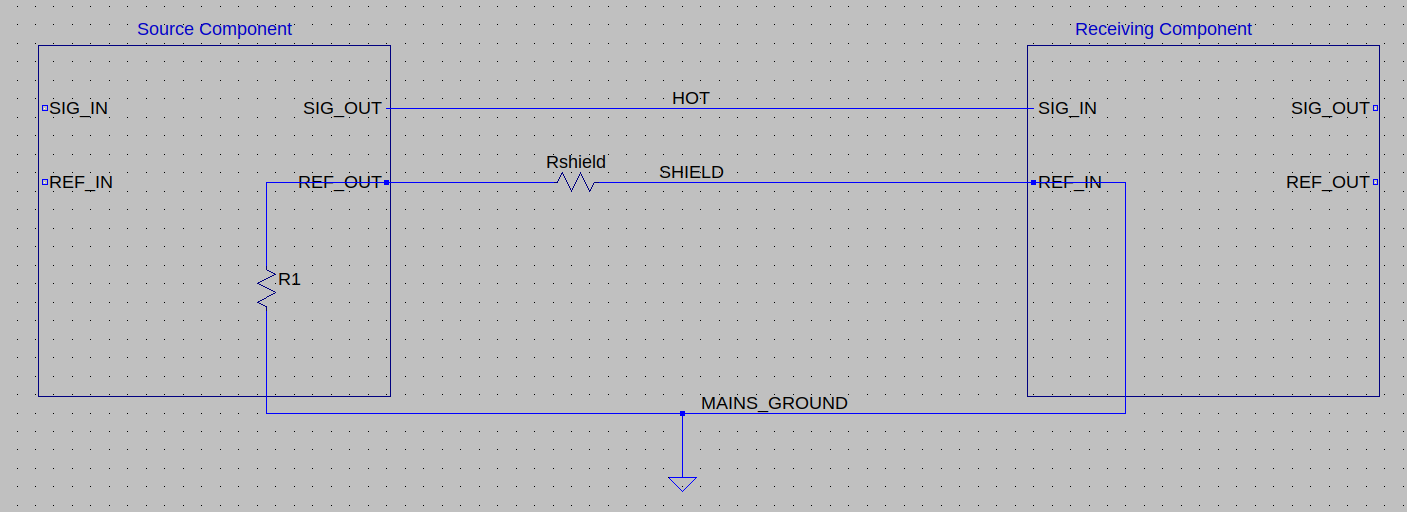
Magnetic flux through the loop will induce currents, which flow across the finite resistance of these wires and induce voltage drops. And while the cumulative voltage around the entire loop must be zero (Kirchoff's voltage law) any given sub-segment of the loop may see a voltage drop, notably the shield of the unbalanced connection.
We can fix this at either end of the connection, by adding a small "ground break resistor" of 5 to 10 ohms between the shield and safety ground. This greatly reduces loop currents. In the diagram, if R1 >> Rshield, most of the EMF-induced voltage will appear across the resistor and not across the shield wire itself.
2) "Local" Ground Loops
Suppose we have a two-channel setup with two RCA cables connecting two components. If their shields meet at both the source and then again at the receiver, the shields form a loop. This loop could induce an error voltage between the source shield and the receiver shield.
We can fix this at either component by simply not shorting the shields together, but ensuring that there are a few ohms between them. If each shield is connected to local ground with a small ground break resistor as above, then we already have a few ohms from one shield to the next.
What errors is unbalanced NOT susceptible to?
A) Impedance mismatch effects
Suppose the output jack and input jack are close together (eg. two components stacked atop one another) and we use a long cable to connect them. Each conductor in the cable forms a mostly-complete loop.
Both shield and hot follow the same path through space, so they should enclose the same magnetic flux. Does this flux induce identical voltages in both shield and hot, such that the errors cancel? Or does it induce a different voltage due to the impedance imbalance?
It's identical and will cancel.
Maxwell says that if you have changing magnetic flux through a loop, you have a circular electrical field in that loop. If the loop is conductive, current will flow and induce an opposing magnetic field.
And while induced current in the shield will create an opposing magnetic flux, the total flux (original plus opposing) is the same through both the shield and the hot wire. Thus the induced voltage should be equal.
B) Capacitive coupling
The shield protects the hot wire from capacitive coupling, but the shield itself is susceptible to capacitive coupling from nearby mains wiring.
The shield's impedance at each end is low so its voltage bounce should be minimal, and most of this voltage bounce appears at both the source and receiver ends equally and will be canceled.
On the other hand, capacitive coupling could induce a current into the wire that flows (in the worst case) to only one end and thus introduces a voltage drop across the shield. How much of a problem is this? Assume the shield has a resistance of .1 ohm, and the nuisance voltage is 120VAC 60Hz. Let's assume that the AC conductor lies right next to the RCA, so let's model this as a parallel plate capacitor with area of 1cm x 1m and a distance of 3mm. That's only 30pF.
At 60Hz, the impedance of 30pF is around 10^8 ohms. In series with 0.1 ohms it forms a voltage divider that allows 1 part in 10^9 of the AC signal to couple into the shield -- that's 120nV. If our nominal signal level is 120mV (it's probably more) then the error is one-part-per-million, or 120db below the signal. If that's our biggest worry, we've won.
Conclusions
Compared to balanced, it's less obvious that unbalanced can be done right -- but it can and with low implementation complexity.
Please comment if there's a source of error I've missed.
It's nice that not every component in the chain needs to be designed carefully. For any single connection, it's enough for either the source component or the receiving component to follow best practices and isolate shields from each other and from local ground. In a typical home setup with some sources, a preamp, and a power amp, it would be enough to design the preamp carefully. Other components could use neanderthal shield-to-chassis grounding, and we could use unbalanced signaling throughout, and there should be no loss of signal integrity.
Let's Define Some Terms
Low impedance: tens of ohms or less.
High impedance: several kilohm or more.
Unbalanced connection: a two-wire cable, typically RCA, with a shield wire and a "hot" signal wire. The shield at each end sees a low impedance. The hot wire sees low impedance at the source and a high impedance at the receiver.
What errors is unbalanced susceptible to?
1) "Global" Ground Loops
This is the traditional ground loop. If both the source and receiver connect the shield to chassis and to mains safety ground, we get a loop. Assume both R1 and Rshield are tiny:
Magnetic flux through the loop will induce currents, which flow across the finite resistance of these wires and induce voltage drops. And while the cumulative voltage around the entire loop must be zero (Kirchoff's voltage law) any given sub-segment of the loop may see a voltage drop, notably the shield of the unbalanced connection.
We can fix this at either end of the connection, by adding a small "ground break resistor" of 5 to 10 ohms between the shield and safety ground. This greatly reduces loop currents. In the diagram, if R1 >> Rshield, most of the EMF-induced voltage will appear across the resistor and not across the shield wire itself.
2) "Local" Ground Loops
Suppose we have a two-channel setup with two RCA cables connecting two components. If their shields meet at both the source and then again at the receiver, the shields form a loop. This loop could induce an error voltage between the source shield and the receiver shield.
We can fix this at either component by simply not shorting the shields together, but ensuring that there are a few ohms between them. If each shield is connected to local ground with a small ground break resistor as above, then we already have a few ohms from one shield to the next.
What errors is unbalanced NOT susceptible to?
A) Impedance mismatch effects
Suppose the output jack and input jack are close together (eg. two components stacked atop one another) and we use a long cable to connect them. Each conductor in the cable forms a mostly-complete loop.
Both shield and hot follow the same path through space, so they should enclose the same magnetic flux. Does this flux induce identical voltages in both shield and hot, such that the errors cancel? Or does it induce a different voltage due to the impedance imbalance?
It's identical and will cancel.
Maxwell says that if you have changing magnetic flux through a loop, you have a circular electrical field in that loop. If the loop is conductive, current will flow and induce an opposing magnetic field.
And while induced current in the shield will create an opposing magnetic flux, the total flux (original plus opposing) is the same through both the shield and the hot wire. Thus the induced voltage should be equal.
B) Capacitive coupling
The shield protects the hot wire from capacitive coupling, but the shield itself is susceptible to capacitive coupling from nearby mains wiring.
The shield's impedance at each end is low so its voltage bounce should be minimal, and most of this voltage bounce appears at both the source and receiver ends equally and will be canceled.
On the other hand, capacitive coupling could induce a current into the wire that flows (in the worst case) to only one end and thus introduces a voltage drop across the shield. How much of a problem is this? Assume the shield has a resistance of .1 ohm, and the nuisance voltage is 120VAC 60Hz. Let's assume that the AC conductor lies right next to the RCA, so let's model this as a parallel plate capacitor with area of 1cm x 1m and a distance of 3mm. That's only 30pF.
At 60Hz, the impedance of 30pF is around 10^8 ohms. In series with 0.1 ohms it forms a voltage divider that allows 1 part in 10^9 of the AC signal to couple into the shield -- that's 120nV. If our nominal signal level is 120mV (it's probably more) then the error is one-part-per-million, or 120db below the signal. If that's our biggest worry, we've won.
Conclusions
Compared to balanced, it's less obvious that unbalanced can be done right -- but it can and with low implementation complexity.
Please comment if there's a source of error I've missed.
It's nice that not every component in the chain needs to be designed carefully. For any single connection, it's enough for either the source component or the receiving component to follow best practices and isolate shields from each other and from local ground. In a typical home setup with some sources, a preamp, and a power amp, it would be enough to design the preamp carefully. Other components could use neanderthal shield-to-chassis grounding, and we could use unbalanced signaling throughout, and there should be no loss of signal integrity.
Attachments
Last edited:
Not a good idea. The shield impedance must never be compromised and that includes the connection resistance to the local reference potential. Why? See below.2) "Local" Ground Loops
Suppose we have a two-channel setup with two RCA cables connecting two components. If their shields meet at both the source and then again at the receiver, the shields form a loop. This loop could induce an error voltage between the source shield and the receiver shield.
We can fix this at either component by simply not shorting the shields together, but ensuring that there are a few ohms between them. If each shield is connected to local ground with a small ground break resistor as above, then we already have a few ohms from one shield to the next.
Also, your idea takes care of the symptom, not the cause. Better avoid the root cause, that is, twist both channel's interconnects together so that i) the loop area is small to begin with, and ii) any potential pickup mostly cancels itself by the well-known effect of twisted cable.
And for the "classical ground loop":
Most of the error signal isn't from magnetic pickup (which easily can be minimized) but rather voltage drops along internal and external ground/PE connections from non-zero currents, and sometimes there is also direct magnetic coupling. The responsible currents can come from capacitors in mains filters (Y-caps) but the typical offender is internal power supply current routed suboptimally so that the ripple charge current causes error voltage drops along shared conductor paths. Failed attempt at proper start grounding, and/or suboptimal wire dress even when star ground rules are obeyed.
Btw, the "classical ground loop" also exist with ungrounded equipment (class-II, 2-prong power supplies). It's all about the amount of capacitive mains coupling. The main offender here are switch-mode power supplies which have a 2.2nF or so EMC-cap from primary to secondary side, and the voltage on the primary side often is the half- or full-wave rectified mains.
The general rule for unbalanced connection is simple, and you've basically addressed that well: Make the audio connection path of the reference potentials the dominant path, it's as simple as that.
Achieved by i) using interconnect cables with lowest shield resistance (and one can add additional thick conductors externally to connect all the audio grounds together, or even use a ground plane/grid, forming a zero-signal reference plane, "ZSRP"), and ii) make the connection to the mains as high impedance (common-mode) as possible. Normally, the internal supplies of class-II should take care of it, and mostly did in former times (using small EI- or CI-core transformers, preferably with seperate bobbins for primary and secondary windings) but today, notaby with SMPS's of the cheaper variety, things are not so simple anymore.
With two or more class-I (3-prong) devices using "ground breaker" circuits between audio GND and chassis does help a lot, the typical circuit being antiparallel diodes paralleled with a resistor and/or capacitor. This requires a supply that is rated for class-II duty (many commercial designs violate code here).
A workaround solution is to use the thinnest and longest mains cable you can find, ideally coiled up (common-mode inductance). A modern(!) 50ft or 100ft cable drum is a quite good solution. "Modern" means a) plastic bobbin and b) it has built-in overheating protection because the power dissipated in the cable cannot find a way to the ambient when coiled up. Unless you're connecting monster class-A power amps and such the current drawn by audio equipment is low enough to fulfil the derated power capacity of a coiled up cable drum.

I am not going to comment the OP's post, or subsequent ones, but KSTR offers a clever and sensible analysis of the most probable issues:
I couldn't have written it better.
There is of course a lot more that can be said, but basically with common sense, no preconceptions, and rational thinking helped by measurements, tests and experiments one can generally solve the most thorny issues.
Some can sometimes resist, but the collective intelligence of a forum may help, should the case occur.
- Status
- This old topic is closed. If you want to reopen this topic, contact a moderator using the "Report Post" button.