Before starting the project, first I would like to check if similar thing already exists, and secondly, if it makes sense at all...
I plan to base it on LDR Pre MkII code:
https://www.diyaudio.com/forums/ana...dr-pre-mkii-ldr-volume-control-switching.html
which means 2.42" OLED display, dual rotary encoders, IR remote, 4 input channels and 2 output channels switched by relays, only PGA2320 instead of LDRs. Additional features available from ESP32 would include web interface for channel switching and volume control, and potentially even A2DP BT audio streaming.
Why PG2320 instead of LDRs? It's simpler to use, much lower distortion and coloration, which some might prefer as opposed to LDRs. I heard PGA2320 in M3Si and I liked it a lot.
Sounds straightforward enough. PGA2320 based preamp projects have been around for a while but yours may be the first ESP32 based one.
The devil is probably going to be in the details - choosing a gain structure and associated circuitry that is getting the most out of the PGA (hint: you can probably do with a 9 dB or so attenuation at the output - sparing an additional relay would enable a high output setting if needed), getting the layout and wiring right, and getting the network connection into the outside world (WiFi inside a metal case is going to be of little use so connectors for external antennas may be required, plus the potential for ground loops introduced via Ethernet cable shield, which could be a real can of worms).
IMHO any new, modern preamp design in this day and age should also include a balanced output (output gain perhaps the common +6 dB over unbalanced) and at least one such input (input gain -6 dB). Observe AES48-2005 pin 1 wiring practices. Circuitry wise, you could go either for dedicated balanced receivers and transmitters (e.g. THAT12xx series) or something with discrete opamps. The former are generally proprietary but compact and easy to apply (and some very high performance, too), while the latter give you more flexibility in parts choice but the builder will have to hand-match components.
Now with Ethernet cable shield and balanced I/O you have multiple possibilities for the case to be earthed. (You might as well consider going IEC Class I altogether at this point.) This would get you in trouble with any unbalanced connections from an IEC Class I device such as a typical PC.
You could do as Bruno Putzeys suggested and use balanced receivers on all inputs (plus ground-compensated output drivers for the balanced outputs), but then what do you do with rogue sources whose power supply mains filter has a tendency to pull signal ground towards 1/2 mains frequency?
Practical designs might have 1 kOhm || 10-100 nF from RCA ground to (chassis) ground, which could be used to also address the potential RF problems introduced when RCA connectors have to be kept isolated from the chassis. It doesn't exactly do practical CMRR any favors though. I imagine builders won't be too enthused when they have to install insulated RCA jacks with RF bypass caps to chassis either.
This might all sound like a massive can of worms, but in fact it's one that is already open as-is. The old hi-fi design philosophy of using unbalanced connections and just floating all devices so they don't disagree on ground levels is becoming more and more untenable in this age of computing devices and networking everywhere. One might as well tackle the bull by the horns.
If you basically just want this as an upgrade for your existing design while accepting the drawbacks of traditional hi-fi, your main problem would be addressing the networking-related issues: Find an Ethernet jack with a shield at least well-insulated from surrounding chassis (it may still be nice to have available for an RF connection via pF-nF), find out what to do with the WiFi antenna(s).
A multilayer board could probably be bulletproofed to the point where a metal chassis is not even required, but how common are wood or plastic cases for such projects? Not to mention that the choice of case may also affect PCB design choices such as grounding layout (the case back is often used as a star ground, for example). I'm afraid a holistic design approach is very much necessary!
")
Pay attention to the radio part of ESP32.
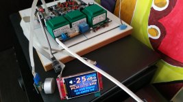
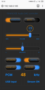
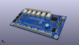
I used ESP32 with PGA2311 in one of my USB DAC project. I have made my own PCB, except for the ESP32 adapter plate, which I have bought from Aliexpress, the white PCB in the pictures below.
The USB to I2S chip, XMOS, has a few I/O pins connected to some ESP32 I/O pins. They are like F0...F3 pins from Amanero board. Every time one of these pins goes high, to tell ESP32 that it is 24.xxx related sample rate (48kHz, 96kHz, etc), the web server freezes (web based remote control). It took me a while to figure out that it is an issue related to WiFi antenna. After I spent 2 days checking the software, I have found that there is no issue in 1 meter range, near my router, so there is a problem because of the poor design of that white PCB adapter for ESP32: in a certain combination of the ESP32 I/O pins state, its PCB antenna dramatically loses the signal strength, because of the PCB traces below of it that shouldn't be there.
Attachments

Buying an ESP32 module recently for a project and did some reading as the modules had been revised since I last looked.
There are now 2 ESP32 modules available - WROOM-32D and WROOM-32U
Specifically, D has an improved RF antenna built in, U has a socket for an external antenna. They also improved the RF circuitry inside the chip itself. The modules are pin and binary compatible with the older WROOM-32 module.
Hope that helps.
Before starting the project, first I would like to check if similar thing already exists, and secondly, if it makes sense at all...
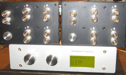
Many years ago I made an 8-channel preamp with 2 PGA4311 chips, and eventually used that circuitry to make a volume-compensated relay switch box. You can switch between speakers using relays and each switch position has the volume controlled by the PGA4311.
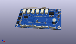
Recently, one of the two boxes I made broke--the spring tension on the flex cable to the LCD caused that connector to fail, so I made a new CPU board using the Heltec ESP32 WiFi module. The updated display is a Nextion 3.2"module, which fit OK in the front panel opening after a bit of cutting on the inner chassis. There isn't an antenna connector on the Heltec module, but you can solder an antenna wire to the printed "F" antenna printed on the board. I used one of these, and it improved the ESP32 signal strength by about 6dB. I epoxied that antenna to the outside of the chassis--it looks nice and works great.
One of the two boxes I made is mostly finished. You can navigate through the menu with the rotary encoders or IR controller. A new feature is Bluetooth control via a simple cell phone app. I'm just using the MIT App Inventor tools for the cell phone app and I'm hoping that the IOS tools will get released soon--already got the Android version working OK.
One problem I ran into is that there are some issues using the Arduino remote control library and the EEPROM library. Read through this if you are using that combination and want to save yourself some grief.
To answer your questions: yes, a similar thing already exists, and yes, it makes good sense to go this route. Cell phone control is a lot nicer than those cheezy remotes, and the ESP32 is a powerful and fun chip to work with. It's also got enough resources to implement the MQTT client. I've got that running on a different project, but decided on Classic Bluetooth for this upgrade.
Another thing to be careful about: the Heltec ESP WiFikit V1 and V2 chips use a somewhat different pinout for the voltages, and the V2 chip generates a lot of smoke if you put it in a V1 socket.
Here's a pic dated 2008 of one of the original boxes. I can take pictures of the updated version if there is any interest.
Attachments

I was disappointed to see a lack of eeprom in ESP32, since my solution uses it extensively. So I revisited the idea with Arduino + PGA2311, until I figure out how to resolve ESP32 issues.
EEPROM functionality in ESP32 comes with NVS (non-volatile storage). I haven't done it myself, but these guys have:
GitHub - sle118/squeezelite-esp32: squeezelite ported to esp32
They turn an ESP32 into a streaming device, something you mention in your first post.
Have you considered an ESP8266?
EEPROM functionality in ESP32 comes with NVS (non-volatile storage). I haven't done it myself, but these guys have:
GitHub - sle118/squeezelite-esp32: squeezelite ported to esp32
They turn an ESP32 into a streaming device, something you mention in your first post.
Have you considered an ESP8266?
Ah, did not know that ESP8266 had an EEPROM. Anyway, I ordered PCBs already, so will play with Arduino version for a while, hear how it sounds before moving to other options.

- Status
- This old topic is closed. If you want to reopen this topic, contact a moderator using the "Report Post" button.
- Home
- Source & Line
- Analog Line Level
- ESP32 driven PGA2320 preamp/IO switcher