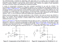
I've seen this in many mixer applications where they don't respect that ratio as to compensate for input impedance.Here's a j-fet input capacitance too.usually they make thousands of tests before choosing some values . OPA2228 is stable for gains of 5x (10k/22k...)and at 10x it will drive 1...1.5nf without compensation...but that 22pf over the feedback resistor looks exactly like a compensation capacitor. And unless I missed something, the divider ratio of 16k/3k9 in the ground compensation does not match 100k/22k too well either... why didn't they go with e.g. 10k/2k2 instead?
He said OPA213x had become rather too expensive for his tastes. Also, with those 100ps I reckon a unity-gain stable part would be good, so OPA2227 instead of 2228.
")
Attachments
Last edited:
I'm not following you here-----?? I don't see a 3.3K Ω R46/45 anywhere.Basically looks good. You missed the 3k3 input resistor (R46 or R45?)
So, a BC549 or a 2N3906 here?.... Q2/4 are likely to be a waste of some perfectly good ZTX450s
That's EXACTLY what it is---I figured to just leave the input pad & switch as is.... there is no reason not to leave R7/9 at 4k7 (or is that supposed to be the combination of 3k9+470 || 4k7?)
I'm not understanding "common-mode swing down"..... and you could go down to 1k-1k5 for R3/10 to get the common-mode swing down at this point, but other than that...
Those parts (OPA2227/28) are even MORE expensive than the OPA2134!! Even with my concocted SOIC-8 to DIP-8 adaptors (~74¢), the OPA1642 is less $$$, and a fine performer....He said OPA213x had become rather too expensive for his tastes. Also, with those 100ps I reckon a unity-gain stable part would be good, so OPA2227 instead of 2228.
I'm not following you here-----?? I don't see a 3.3K Ω R46/45 anywhere.
2N3904*So, a BC549 or a 2N3906 here?
Or most everything else comparable you might have on hand, except maybe a 2N5210.
According to sim, using 2N4403 as inputs yields 1.188 nV/√(Hz) at 2 kHz with 2N3904, 1.212nV/√(Hz) with BC550 (On Semi) and 1.228 nV/√(Hz) with 2N5210, using Bob Cordell's models. (RB = 30.1, RB = 167 - vs. RB = 900 for 2N5210, maybe some Central Semiconductor cheapies - similarly high Rbb' has also been noted for cheap BC550s.) So apparently you still slightly benefit from lowish Rbb' while beta only needs to be moderately high. 2N4401 (RB = 13) also works well, at 1.204 nV/√(Hz). Guess you shouldn't be using parts from the very cheapest manufacturer...
According to simulation, some of the input is being converted into common-mode voltage at the opamp inputs - I've seen 2 Vpp or so. The amplitude of that scales with collector resistor value. So best choose that no larger than necessary to get DC levels comfortably away from the supplies. Thankfully the OPA164x input stage seems to be pretty much upside down from the TL07x, meaning it'll gladly work down to V- and even a bit below.I'm not understanding "common-mode swing down"
But don't go too low altogether, as (10k||100p)/Rc determines your opamp noise gain and hence how much remains of your opamp GBW. At 500 ohms the whole thing would be as fast as the original TL072 and configuration, so I wouldn't go below that for sure.
Like I said, 1k sounds like a good compromise.
Attachments
Last edited:
PS: Input transistor current varies slightly between various npns, which may explain part of the difference in noise - from 932 µA (BC550) to 1.03 mA (2N3904). 2N5210 949 µA, 2N4401 955 µA. So the 3904 "cheats" a bit as well, and the BC550 actually does decently. Absolutely speaking, the differences do remain minimal though.
Yes, I see R46 (3.3K) now; my bad. I guess I just overlooked it because I didn't see any need for it---what does it accomplish?
Yes, 2N3904, not 6---got my polarities mixed up.
Horowitz-Hill shows 2N3904 as rbb=110, not the 30.1 that you mention---????
Actually, I was just gonna leave the NE5532s and circuitry as is. Just get rid of the compromise-filled TL072s everywhere. OPA 1642s on the input boards and LM4562s on the output tape returns.
So, if I may ask your indulgence, what noise/distortion does simulation show for ZTX550/450s with OPA1642?
Last edited:
> what does it accomplish?
Connect a long mike cable but do not connect a microphone.
The stock 94k(?) input will catch all the buzz and half the RF in the room.
A 3k input picks up much less crap.
"Most" console marketers favor the later behavior. Open inputs are not normal. But they happen. And LOUD open inputs un-nerve the potential buyer.
There's a sub-dB loss of S/N but few can tell. Indeed YOU can chose to omit the 3k, and close your ears when you mess with open cables.
AHA! Thank you, PRR, for your astute reply!A 3k input picks up much less crap.
So, the Complementary Feedback Pair works so well in my mic preamp application, I was wondering if it could also improve the performance of this tape head reproduction amplifier by simply replacing Q1 with my Zetex pair (550/450) of transistors and 680Ω resistor. I'd also change the LM318 for an NE5534A. I'm showing a 2N3906 (what was available on SiMetrix) but the actual transistor is a "CD701" which I have not been able to find ANY information on.
Attachments
Last edited:
I see your point. Schematic corrected. Also finally found the mysterious Ampex transistor---it's a 2N3964, a low-noise PNP with exceptionally high Beta, which is quite expensive these days.I do not believe your "Repro head" connection is correct. Here is how I see Ampex's plan:
Attachments
Inner SHLD drives-out the cable capacitance. Long cable? But also probably a fairly hi-Z head. Which meshes with use of hi-hi-Beta transistor at 100uA. OSI is probably near 10k in the critical band (for tape, probably 2kHz-8kHz). I suspect it would be very hard to improve on an Ampex. (Yes, I know people do ALL sorts of mods to their Ampexes...)
22uH? That does nothing in the audio band. Probably to cut bias-tone or even so it always works under a hi-power radio tower.
A selected 2N5087 would work OK in there. Finding the best (lowest hiss) from a bag of 100 might put you within a dB of the magic Ampex part (which may have been further selected from run-of-mill 2N3964) and '87 is dirt cheap (tho the thru-hole may be out of stock). Of course low-low electrical hiss may be moot once the tape starts to move.
might help youI see your point. Schematic corrected. Also finally found the mysterious Ampex transistor---it's a 2N3964, a low-noise PNP with exceptionally high Beta, which is quite expensive these days.
https://corescholar.libraries.wrigh...om/&httpsredir=1&article=1557&context=etd_allNO doubt---the Ampex ATR-100 is/was the finest analog tape recorder ever built. Still, maybe room for tinkering...when Allistair designed the ATR, he used the hottest-shot IC available at the time---the LM318 was the fastest. Had the NE5534 been available at the time (it was still several years away), I believe he would have used that.I suspect it would be very hard to improve on an Ampex. (Yes, I know people do ALL sorts of mods to their Ampexes...)
I think it was a bias blocker. The ATR uses an unusually high bias frequency (432 KHz).22uH? That does nothing in the audio band. Probably to cut bias-tone or even so it always works under a hi-power radio tower.
Yes, that's true. I was just thinking of maybe adding an NPN transistor to the existing 2N3964 in CFP fashion. Rod Elliott said "The compound pairs of 2N4403 and BC549s are far more linear than any single transistor." So I was thinking that a CFP arrangement might be an improvement.A selected 2N5087 would work OK in there. Finding the best (lowest hiss) from a bag of 100 might put you within a dB of the magic Ampex part (which may have been further selected from run-of-mill 2N3964) and '87 is dirt cheap (tho the thru-hole may be out of stock). Of course low-low electrical hiss may be moot once the tape starts to move.
I have found one more troubling aspect of my Soundcraft 200's input circuitry----the Line/Mic switch is directly in front of the mic preamp. While this certainly gives the ability to adjust the level of the incoming line-level signal, it leaves the possibility of hitting the preamp with a signal ~ 55 db hotter than a microphone input, and that seems a sure path to distortion. I am thinking to move the switch to the inputs of the op amp, with 10 KΩ/47uF in series with the line inputs; thus leaving the transistor preamp for mic use only.
> Line/Mic switch is directly in front of the mic preamp.
With a pad, surely?
Yeah, no pad seen in manual. But also the Phantom is not shown on the Mic input. I suspect there is stuff on the back panel not on the board, not shown in this manual.
Also <3k is a low Z for Line. A couple 15k in series would give 20dB pad and nice input Z.
With a pad, surely?
Yeah, no pad seen in manual. But also the Phantom is not shown on the Mic input. I suspect there is stuff on the back panel not on the board, not shown in this manual.
Also <3k is a low Z for Line. A couple 15k in series would give 20dB pad and nice input Z.
Last edited:
Excuse me if I have a few things to catch back up on.
I believe that they are essentially equivalent and in fact any possible combination of CM and DM input resistances should yield exactly one set of resistor values for each - might be a good candidate for another calculator. Actually, it's the same exact two versions you've got for a differential amplifier tail as well. (This preamp uses the "pi" type as it enabled the use of a single pot for gain setting.) They converge into one if you remove all emitter degeneration.
I hope you've got a scope for troubleshooting.
Plan B, stack two TL072s. They can be paralleled almost indefinitely thanks to their high internal output impedance, though of course input impedance grows accordingly.
Plan C, honestly a better FET input part like OPA1642 should work well here as well...
Speaking of tape returns, I noticed that their balanced input receivers have got 100 pF in parallel to the feedback R in one leg but not in the other. Oops. If the real circuit is the same, this oversight should be corrected, otherwise high-frequency CMRR is rather compromised.
All in all I would expect slightly lower input noise still.
The question also is how much could be gained in the first place - we are talking about a tape application after all. What if tape distortion already dominates head preamp distortion as-is? (If the tape gives you H3 at -50 dB, it's hardly going to matter whether your electronics contribute H2 at -60 or -80 dB.) Are you even sure that the playback side is the weak spot?
Are you sure there aren't any series resistors in the LINE input wiring just yet? That's how most everyone else does it, although ideally you'd want a proper double-L type attenuator to reduce common mode and effective source impedance as well. (As PRR says, there may well be circuitry not depicted - I noted the missing phantom power feed earlier, too.)
Unattenuated, I would expect the input to handle about +7 dBu (assuming the 5k pot you indicated, otherwise maybe 3 dB more). If you want to stretch this to +22 dBu, simulation reckons 6k2 in series each would be a good bet.
Speaking of inputs, I wonder what this unit's relationship with AES48-2005 guidelines might be. It could be that it's actually compliant, with pin 1s routed to chassis at all inputs and outputs and a central connection to power GND somewhere, e.g. on the input panel. I can't tell though.
While PRR has already answered this one, let me mention that this "pi" kind of input topology (the one 3k3 "beam" in the middle and two 4k7 "legs") is one way of reducing differential-mode input impedance while leaving common-mode input impedance as-is. The alternative is a T-type with one resistor coming up from ground and splitting into two more resistors going to each input.Yes, I see R46 (3.3K) now; my bad. I guess I just overlooked it because I didn't see any need for it---what does it accomplish?
I believe that they are essentially equivalent and in fact any possible combination of CM and DM input resistances should yield exactly one set of resistor values for each - might be a good candidate for another calculator. Actually, it's the same exact two versions you've got for a differential amplifier tail as well. (This preamp uses the "pi" type as it enabled the use of a single pot for gain setting.) They converge into one if you remove all emitter degeneration.
That's actually correct. I think that just shows how much this parameter may vary from manufacturer to manufacturer alone. You can't get much more jellybean than a 2N3904, now can you? I would not be one bit surprised to find that the world of jellybean transistors is quite a messy place, with different kinds of manufacturers putting different stamps on their different ranges of silicon. Rbb' is not a parameter that manufacturers really like to document, just because it might change even when they have to source a transistor from a different process for some reason.Yes, 2N3904, not 6---got my polarities mixed up.
Horowitz-Hill shows 2N3904 as rbb=110, not the 30.1 that you mention---????
LM4562s are maybe a tad heavy on current noise. In the tape return input circuits (7k5/7k5 balanced receiver), they'd be barely any less noisy than the TL072s! (Mind you, in the next stage they would be, potentially even more so with feedback network resistor values reduced to e.g. 6k2/2k2 or 4k3/1k5.) Other than that they should work well assuming you can get them stable.Actually, I was just gonna leave the NE5532s and circuitry as is. Just get rid of the compromise-filled TL072s everywhere. OPA 1642s on the input boards and LM4562s on the output tape returns.
I hope you've got a scope for troubleshooting.
Plan B, stack two TL072s. They can be paralleled almost indefinitely thanks to their high internal output impedance, though of course input impedance grows accordingly.
Plan C, honestly a better FET input part like OPA1642 should work well here as well...
Speaking of tape returns, I noticed that their balanced input receivers have got 100 pF in parallel to the feedback R in one leg but not in the other. Oops. If the real circuit is the same, this oversight should be corrected, otherwise high-frequency CMRR is rather compromised.
Any simulation is only ever as good as the models used, and I'm afraid I wouldn't trust the Zetex / Diodes Inc. SPICE models very much when it comes to Rbb' in particular. I have no idea how they were modeling their parts, but their RB does not look very realistic - you barely ever find anything even higher than 10 ohms, and 2-3 ohms max more often than not. The ZTX450 model, last revised in 1990 (!), say RB=1.1, and ZTX550, last revised in 2001, even claims RB=0.16! Horowitz/Hill claim a more sensible 8.5 and 7.7 ohms, respectively. ZTX450 Early voltage VAF is supposed to be 109.45, while the book reckons it's a whopping 730 volts! CJC = 15.8p does roughly match a 15 pF Cob at least.So, if I may ask your indulgence, what noise/distortion does simulation show for ZTX550/450s with OPA1642?
All in all I would expect slightly lower input noise still.
That's a much tougher one. For one thing, this circuit is more intricate with both feedforward and feedback for some reason, plus extra compensation. I definitely do not fully understand it. We would have to come up with some more current, too, as the input transistor appears to run at little over 100 µA, no doubt in order to keep current noise down. Anyone got a clue what the inductance of a tape head like that would be? I am reminded of a phono MM application here, maybe a bit lower impedance.So, the Complementary Feedback Pair works so well in my mic preamp application, I was wondering if it could also improve the performance of this tape head reproduction amplifier by simply replacing Q1 with my Zetex pair (550/450) of transistors and 680Ω resistor.
The question also is how much could be gained in the first place - we are talking about a tape application after all. What if tape distortion already dominates head preamp distortion as-is? (If the tape gives you H3 at -50 dB, it's hardly going to matter whether your electronics contribute H2 at -60 or -80 dB.) Are you even sure that the playback side is the weak spot?
I guess you could do that, but it seems like it would be quite messy.I have found one more troubling aspect of my Soundcraft 200's input circuitry----the Line/Mic switch is directly in front of the mic preamp. While this certainly gives the ability to adjust the level of the incoming line-level signal, it leaves the possibility of hitting the preamp with a signal ~ 55 db hotter than a microphone input, and that seems a sure path to distortion. I am thinking to move the switch to the inputs of the op amp, with 10 KΩ/47uF in series with the line inputs; thus leaving the transistor preamp for mic use only.
Are you sure there aren't any series resistors in the LINE input wiring just yet? That's how most everyone else does it, although ideally you'd want a proper double-L type attenuator to reduce common mode and effective source impedance as well. (As PRR says, there may well be circuitry not depicted - I noted the missing phantom power feed earlier, too.)
Unattenuated, I would expect the input to handle about +7 dBu (assuming the 5k pot you indicated, otherwise maybe 3 dB more). If you want to stretch this to +22 dBu, simulation reckons 6k2 in series each would be a good bet.
Speaking of inputs, I wonder what this unit's relationship with AES48-2005 guidelines might be. It could be that it's actually compliant, with pin 1s routed to chassis at all inputs and outputs and a central connection to power GND somewhere, e.g. on the input panel. I can't tell though.
Last edited:
Well, I think I'll take your warning about the unconnected long mic cable causing havoc, and leave the 3kΩ resistor in place for the mic circuit. I don't believe the line input will suffer the same danger, as it is wired directly to a patch bay, normalled from the 8-track tape machine output. Then I'll put my 10kΩ/47µF Nichicon Muse in series with each of those +/- line inputs, and I should be good to go. Eh?> Also <3k is a low Z for Line. A couple 15k in series would give 20dB pad and nice input Z.
Well, at line level (1 volt rms), S/N is probably in excess of 100 db, so the noise isn't really a factor there. The TL072s are so feeble at driving anything below 10KΩ that I just want to be rid of them!LM4562s are maybe a tad heavy on current noise. In the tape return input circuits (7k5/7k5 balanced receiver), they'd be barely any less noisy than the TL072s! (Mind you, in the next stage they would be, potentially even more so with feedback network resistor values reduced to e.g. 6k2/2k2 or 4k3/1k5.) Other than that they should work well assuming you can get them stable.
Indeed I do---my trusty old Tektronix 465!I hope you've got a scope for troubleshooting.
Yeah, I had considered that as well, and may still do that. OPA1642 +SOIC-to-DIP adapter = ~ $2.90. Mouser just dropped the price on LM4562s AGAIN to just $1.36 each (qty 10), so they are quite attractive!Plan C, honestly a better FET input part like OPA1642 should work well here as well...
Good eye! Thanks for spotting that---I will definitely patch that error.Speaking of tape returns, I noticed that their balanced input receivers have got 100 pF in parallel to the feedback R in one leg but not in the other. Oops. If the real circuit is the same, this oversight should be corrected, otherwise high-frequency CMRR is rather compromised.
I am struggling with that also---my best guess, from Nortronics head brochures, is about 4K impedance, and 650Ω resistance.That [tape head preamp]'s a much tougher one. For one thing, this circuit is more intricate with both feedforward and feedback for some reason, plus extra compensation. I definitely do not fully understand it. We would have to come up with some more current, too, as the input transistor appears to run at little over 100 µA, no doubt in order to keep current noise down. Anyone got a clue what the inductance of a tape head like that would be?
Definitely true there---I'm thinking that tape noise/distortion overrides any electronic contribution as well; I'm just wondering if a small NPN/680Ω wrapped around the 2N3964 would be slightly better, due to Rod's comment about the CFP combination being more linear than any single transistor.The question also is how much could be gained in the first place - we are talking about a tape application after all. What if tape distortion already dominates head preamp distortion as-is? (If the tape gives you H3 at -50 dB, it's hardly going to matter whether your electronics contribute H2 at -60 or -80 dB.) Are you even sure that the playback side is the weak spot?
I'll check that out.Are you sure there aren't any series resistors in the LINE input wiring just yet?
That's about what I was thinking, and that SUCKS. I'm gonna run the line input around the mic pre---I don't think it will be too messy; we'll see.Unattenuated, I would expect the input to handle about +7 dBu.
Hmmmmm....not exactly following you there. I was gonna put in a ground bus bar ala the "Star Grounding" technique alluded to earlier. Maybe I should just connect all the pin 1s to there.Speaking of inputs, I wonder what this unit's relationship with AES48-2005 guidelines might be. It could be that it's actually compliant, with pin 1s routed to chassis at all inputs and outputs and a central connection to power GND somewhere, e.g. on the input panel. I can't tell though.
Last edited:
So, I've pretty much decided on my CFP mic pre mod, and changing the input board ICs to OPA1642s. The input EQ caps to PPs, and the couplers to Nichicon Muse. Replace the tape return ICs with LM4562s, adding the neglected 100pF cap. Power Supply will be modded with Elvee's denoiser and added ground bus bar, and all 37-year old supply bypass electrolytics replaced. Now the only thing remaining is the bus drivers---which are currently NE5532s, which really are fine ICs for the most part. I could also replace those with LM4562s, which are quieter, cleaner, and faster; but the NE5532s have MUCH more drive current--38mA versus the 4562s 26mA. Is that an issue? I don't know---15 volts peak into 600Ω is only 25mA, so maybe it doesn't matter--??? Probably normally driving much higher input impedance loads (tape machines, audio processors, etc.) but who knows. Also maybe fix the headphone driver with OPA1656s, which will drive 100 mAs---plenty enough for my 150Ω Sennheiser 650s.
Last edited:
- Home
- Source & Line
- Analog Line Level
- Interesting Soundcraft 1600 mod results