I am going to employ the star-grounding technique suggested here: Console Modification: Soundcraft 200b grounding.......it's actually power supply noise thanks to some rather dried-out dodgy Chinese caps and/or thin copper, much like what I'm suspecting for the Soundcraft 200. Resistor matching may not be of the highest standard either.)
And modify the LM317/337 power supply per Elvee:
D-Noizator: a magic active noise canceller to retrofit & upgrade any 317-based V.Reg.
Those mods should clean up the power-supply issues in the Souncraft 200, eh?
THANKS MUCH for your input!
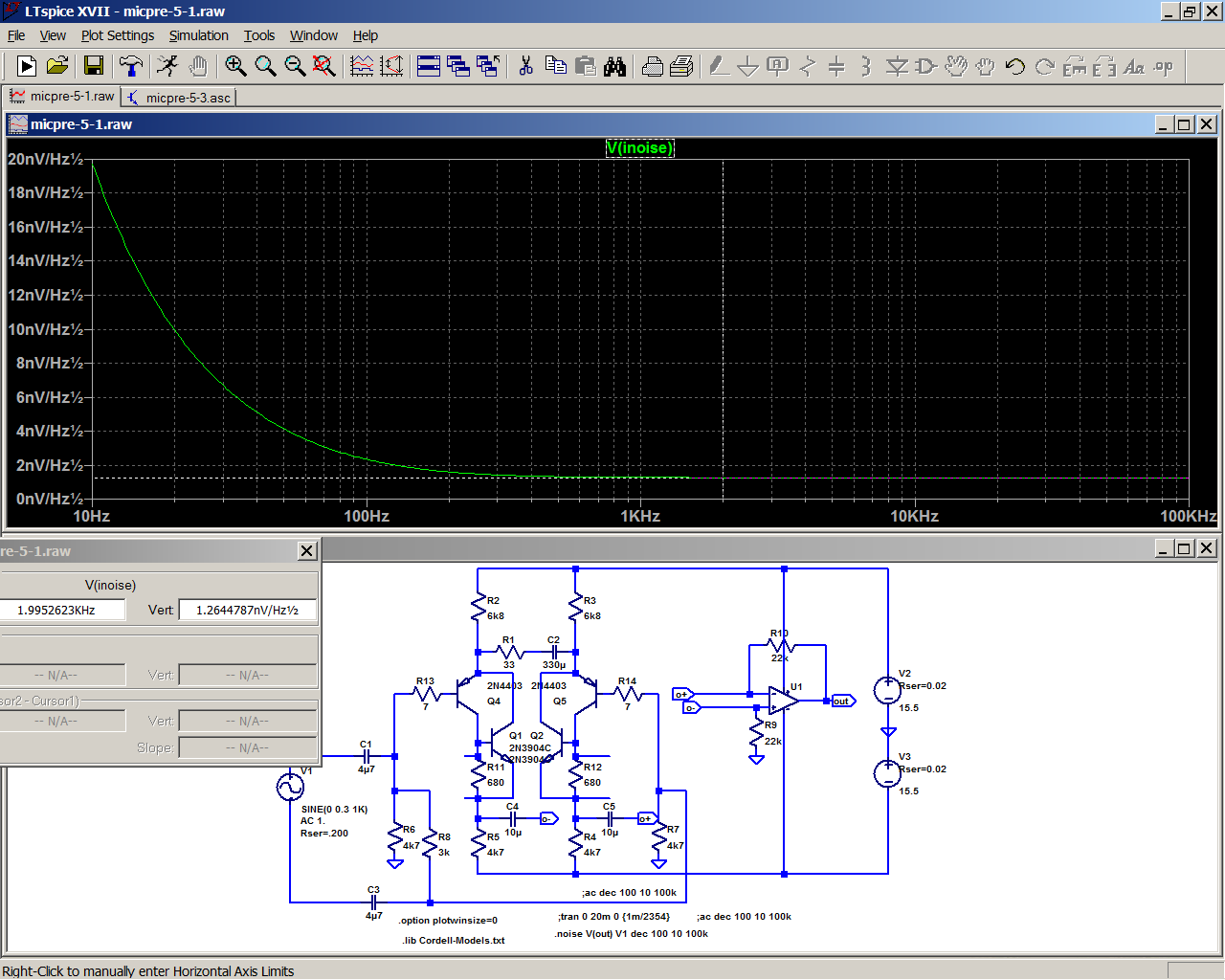
So, you are using 2N4403 + 2SC1815 in the CFP configuration; Rod Elliott (Low Noise Balanced Microphone Preamp) uses 2N4403 + BC549. I was thinking of using ZTX790A + ZTX690B, due to their combination of high beta and low rbb. Is that a problem? In your simulation (sorry, I don't have that capability), which would yield the lowest THD and lowest noise?I meant 2N4403 + 2SC1815 in case that wasn't obvious........I have now revisited my simulations, and lo and behold, the CFP configuration plus increased current does in fact yield a substantial reduction in distortion, in line with the THAT Corp. presentation......With 680 ohm resistors in the CFP and 7k5
You used 680 Ω and 7.5K Ω resistors; the THAT presentation used 750 Ω and 2.87K Ω; Rod used much higher resistance values in his project, which seems counter-intuitive to achieving lowest noise----???? I'm confused...

Last edited:
If I'm reading you correctly, you're saying I could simply mod the existing Soundcraft 200 mic pre by;....I have now revisited my simulations, and lo and behold, the CFP configuration plus increased current does in fact yield a substantial reduction in distortion, in line with the THAT Corp. presentation. With 680 ohm resistors in the CFP and 7k5 instead of the 15ks it's about 7 dB down at highest gain, dropping to about 28 dB down at moderate gains - quite significant. You could still try pushing you luck by going a bit higher with the current, but 6k2 seems to be about the limit before performance at high input starts degrading. I'd say hand-match some 6k8 metal films and be done with it.
1) substituting 6.8 K Ω resistors (matched) for the 15Ks
2) put in 2 x 680 Ω resistors (matched) to replace the 4.7K Ω
3) add a 2SC1815 transistor ala the CFP method
4) perhaps substituting a 1,000µF cap for the existing 100µF cap and a OPA1652 for the TL072
and leave the existing 10K pot as well as the remainder of the circuit.
THAT would be ideal! Will it give me the ~5 db noise/ >20 db THD improvement?
Last edited:
Not quite.
Re: 2), the 680R was referring to the extra resistors in the CFP, the ones in parallel with the base of the npn that set pnp input collector current. Pretty much exactly 1 mA like that.
The 4k7s appear to be part of some sort of monolithic resistor array - it may be hard to change these, so I left them as-is. You may want to look at them in person and determine the feasibility of a mod.
Re: 3), I tried it with various npn transistor models and the difference was marginal. Noise density at 2 kHz varied between 1.265 (2N3904) and 1.30 nv/sqrt(Hz) (2N5210) at full gain, with 2N5551 and BC550 in between. So it seems safe to say that (within reason) you can go by pinout and parts availability. 2SC1815 would obviously be typical Japanese ECB pinout, the others are EBC.
(I added 7 ohms per input transistor base to bring simulated Rbb' up to 17 ohms.)
One potential problem is that maximum gain is up by almost 8 dB (from ~54 dB to ~62 dB, as the feedback loop brings down effective Re from ~26 ohms to much less), and noise at same gain would actually turn out to be slightly higher. Unless you say that more gain would actually be welcome (e.g. to overcome noise in following stages), one would have to tackle the two matched 22ks at the opamp and bring them down to about 9k1... with the reduction in noise gain (about 15.0 dB --> 9.3 dB) being somewhat more than compensated by the heavier output loading.
This could be offset by using a more powerful opamp type, of course. I'd take it easy and try an OPA1642 with some extra rail decoupling underneath first. Keep in mind that reduced noise gain means less stability margin as well.
At the same maximum gain for the CFP version, I'm getting basically the exact same effective input noise (which at ca. -132.5 dBu shorted would be fine by any standard) but roughly 11 dB less distortion. And as state earlier, the advantage grows at lower gain. It's a worthwhile mod for that alone.
You don't actually have to change the 4k7s - input noise could be brought down further by reducing the 33 ohms to 10-15 ohms and a further reduction of the ex 22ks to match the max gain. Stock, max gain is determined by 22k/(33R + 2* Re).
Before you attempt to slap a 1000 µF cap in there, make sure it even fits. Low-voltage parts like 6.3 V are going to degrade relatively quickly if left unbiased; consider a "poor man's bipolar" back-to-back combo if there's enough space.
Attachments

Last edited:
sgrossklass: I cannot thank you enough for the TREMENDOUS help you have given me in improving my cherished little Soundcraft mixer!!
I noticed that you left out the 10K Ω gain pot in your simulation in order to look at it @ maximum gain. In practice, can I still use the existing 10K Ω reverse-log pot and retain a smooth transition from min to max gain?
I believe I have enough room to substitute some small 1/8 watt resistors in place of the resistor array;so would there be any advantage if that be easily done? As for the capacitors, I was planning on using bi-polar MUSE caps as replacements (as these are reputed to have the least distortion, and replacing all the 37-year-old electrolytics seems like good idea), so the biasing won't matter. I'll use as large a replacement that will fit for the existing 100µF that is in series with the gain pot.
I was maybe looking at OPA1652s as TL072 replacements---they are actually SLOWER than the OPA1642s (10v/µSec vs. 20 v/µSec), so they won't pose as much of an oscillation risk, and they are slightly quieter. I seriously doubt the 10 vs 20 slew rate will be audible, especially in light of the 9v/µSec NE5532s that follow later on in the mix buss.
I don't think the max gain will be a problem; and, if it is, as you say, I can always lower the 22K feedback resistor. I also noticed that you included 10µF coupling caps between the transistors and the op amp inputs---- I would guess that is to eliminate any DC offset. I guess I could always match the transistors to eliminate that instead of the caps.
I am wondering if your use of the 6.8K resistors in the emitter circuit is to lower the collector current; the THAT presentation shows 2.87Ks for an Ic of 5 mA----is that excessive?
Indeed, if I can achieve < 2nV√Hz noise performance and a 10-25 db THD improvement, I'll be a VERY happy camper! I actually love all the big-board features (solo buss, 4-band EQ, 4 aux sends, and 8-track monitoring) that this little 8x4x2 mixer offers in a small space.
Again, THANKS! for your help!
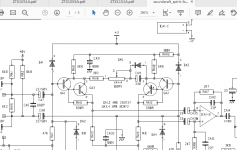
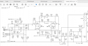
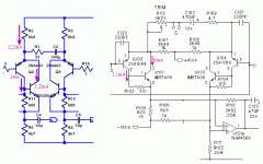
Souncraft sx folio and Mackie VLz1400, Amek 2500 ...plus 2sa1038E, 2sa1016 and their complements and so on and so forth
Attachments
-
 soundcraft.png49.7 KB · Views: 231
 -
 mackie.png68.2 KB · Views: 238
 -
 Amek_2500_micamp.gif32.4 KB · Views: 240
 -
ZTX213_ETC(1).pdf144.5 KB · Views: 60
-
2SA1016(1).pdf55.5 KB · Views: 46
-
2SA1038-Rohm(1).pdf305.7 KB · Views: 68
-
2SA1312_datasheet_en_20140301.pdf309.3 KB · Views: 50
-
2sa1579,1514K,1038S(2).pdf57.2 KB · Views: 50
-
2sa1084-85.pdf47.2 KB · Views: 39
-
2SC2362.pdf64.6 KB · Views: 57
Thanks for the files! Interesting to see how other designs handled the CFP approach. Funny that the AMEK went to the trouble to parallel 4 transistors to improve the noise; then went and stuffed the signal into a NOISY old TL072!
Unfortunately, those old, low-noise transistors are either SMD or unobtanium.
Unfortunately, those old, low-noise transistors are either SMD or unobtanium.
> can I still use the existing 10K Ω reverse-log pot and retain a smooth transition from min to max gain?
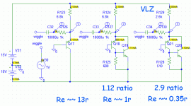
The hiss issue is totally about too much resistance in the 22k+100k/33r+22k network. All three parts should be much lower value! As it is, as soon as you come off maximum gain, output hiss dominates. The VLZ design is a practical limit (Mackie is not so dumb) with 3.9k where you have 22k, *and* 5k pot where you have 100k(!). And 5r in place of your 39r, forcing a huge capacitor also.
I hadn't realized it, but this low-price mixer business may be the reason folks keep bugging me about a mike booster I designed as a joke. If your mike amp is any good, the booster is not needed (stupid). But I guess there are a lot of sub-$5 mike amps out there, and folks who would rather stick stuff inline than tinker inside.
Aside from hiss there is linearity. You want the emitter resistance across the input pair to be very much less than your gain resistor, so Rgain swamps emitter nonlinearity. In the "simple" form, at 2mA, Re is of course 13 Ohms. I didn't think the Szlaki form with very-similar currents would help much, but it helps enough to be interesting. Working at higher ratio helps more.
Attachments
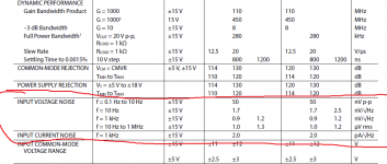
That's what I was thinking also, but Rod Elliott's Mic Pre design (Low Noise Balanced Microphone Preamp) uses 100K/22K and he's claiming 1.9nv√Hz noise performance----???The hiss issue is totally about too much resistance in the 22k+100k/33r+22k network. All three parts should be much lower value! As it is, as soon as you come off maximum gain, output hiss dominates.
well...it's a bit more complex than this...ad797 might be equally good...as the current noise isn't really a big problem with 200ohms dynamic mikes.That's what I was thinking also, but Rod Elliott's Mic Pre design (Low Noise Balanced Microphone Preamp) uses 100K/22K and he's claiming 1.9nv√Hz noise performance----???
Attachments
because we had other discussions on the subject here you have a hand drawing of the input stage for Tascam Portastudio 414 based on njm2068SDThanks for the files! Interesting to see how other designs handled the CFP approach. Funny that the AMEK went to the trouble to parallel 4 transistors to improve the noise; then went and stuffed the signal into a NOISY old TL072!
Unfortunately, those old, low-noise transistors are either SMD or unobtanium.
Attachments
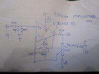
But in the Amek circuit there is a large voltage gain before the TL072 opamp so that its noise is miniscule refered to the input. The voltage gain is variable from about 14 to 1400, so at all but the lowest gain settings the input transistor completely dominate the noise performance. The JFET device allows coupling caps to be film types, not electrolytics.
Last edited:
No change there whatsoever. Even if you do change some of the other resistor values, the pot value will essentially affect minimum gain only.I noticed that you left out the 10K Ω gain pot in your simulation in order to look at it @ maximum gain. In practice, can I still use the existing 10K Ω reverse-log pot and retain a smooth transition from min to max gain?
You could increase tail current even beyond 2 mA and change (further improving CFP linearity), as now the voltage drop across the 4k7s is the limiting factor for distortion at high input amplitude.I believe I have enough room to substitute some small 1/8 watt resistors in place of the resistor array;so would there be any advantage if that be easily done?
I would be somewhat hesitant to do this, however, since voltage drop across RC power filters would increase (though only by less than half a volt) and perhaps more importantly, so would power supply loading times all input channels, and I haven't looked at power margins. Let's say we have +5 mA x2, for 8 inputs that's +80 mA.
I did notice that bringing down the 4k7s slightly worsens distortion but also reduces common-mode signal present at the opamp inputs, so effective CMRR would be up, and common-mode distortion would be down if relevant.
NB: You can't compare BJT and FET input slew rates directly. Generally speaking, BJT slew rate is more "valuable" by as much as a factor of 2 or so. This is due to the differences in differential amplifier characteristics. When plotting output slew rate over input voltage differential, undegenerated BJTs will reach maximum at maybe 60 mV, while FETs show a much more gradual increase and may need a volt or so.I was maybe looking at OPA1652s as TL072 replacements---they are actually SLOWER than the OPA1642s (10v/µSec vs. 20 v/µSec), so they won't pose as much of an oscillation risk, and they are slightly quieter. I seriously doubt the 10 vs 20 slew rate will be audible, especially in light of the 9v/µSec NE5532s that follow later on in the mix buss.
This is just a relic from simulating the 1600 circuit. They are not strictly needed as long as opamp input voltages are kept well within specified common-mode input voltage range at all times - for example, with the TL072 and many other FET input opamps you must keep away from the negative rail by at least 3 V to avoid the nasty effects of inversion. There is about 2 Vpp of common-mode voltage swing at max gain near max output (with 6k8/4k7), so 4 V min it is. On the other hand, you must also keep away from input voltage a fair bit. The ~5 V from negative rail of the original design weren't a bad bet.I also noticed that you included 10µF coupling caps between the transistors and the op amp inputs---- I would guess that is to eliminate any DC offset.
See above - it depends. As I said, you can't do less than about 6k1 (2.3 mA or so) when leaving the 4k7s in, otherwise there is too much voltage drop over those.I am wondering if your use of the 6.8K resistors in the emitter circuit is to lower the collector current; the THAT presentation shows 2.87Ks for an Ic of 5 mA----is that excessive?
All the pot value (which btw is "only" 10k) is going to influence is minimum gain. Not terribly critical. But yes, 22k/33R should ideally be lower, with a more powerful opamp to match.The hiss issue is totally about too much resistance in the 22k+100k/33r+22k network. All three parts should be much lower value! As it is, as soon as you come off maximum gain, output hiss dominates. The VLZ design is a practical limit (Mackie is not so dumb) with 3.9k where you have 22k, *and* 5k pot where you have 100k(!). And 5r in place of your 39r, forcing a huge capacitor also.
Why Rod Elliott chose to have additional resistors in series in P66 is unclear to me. Instead of 100k/22k he could have used 10k/- with same results in terms of minimum gain, and almost 5 dB less noise at low gain. Well, that's 10k of output loading in parallel to whatever load there is. Might be a bit low. You could use 22k/3k0 instead - still almost 4 dB lower noise. A few dB more each with a lower-noise opamp.
Absolutely. Cloudlifters and FETheads do enjoy some popularity, especially among owners of SM7bs and the like. Knocking ~20 dB of gain off the main pre means substantially better distortion performance as well.I hadn't realized it, but this low-price mixer business may be the reason folks keep bugging me about a mike booster I designed as a joke. If your mike amp is any good, the booster is not needed (stupid). But I guess there are a lot of sub-$5 mike amps out there, and folks who would rather stick stuff inline than tinker inside.
Yep. I was just pushing things as far as doable without have to swap out the 4k7s.I didn't think the Szlaki form with very-similar currents would help much, but it helps enough to be interesting. Working at higher ratio helps more.
Hmmmmm.....so you are saying that transistor choice doesn't matter. But putting in the 7Ω base transistor pretty much swamps out any difference between transistors' Rbb. What if you DON"T include the 7Ω? Would it then be advantageous to select a transistor with low Rbb?Re: 3), I tried it with various npn transistor models and the difference was marginal. Noise density at 2 kHz varied between 1.265 (2N3904) and 1.30 nv/sqrt(Hz) (2N5210) at full gain, with 2N5551 and BC550 in between. So it seems safe to say that (within reason) you can go by pinout and parts availability. 2SC1815 would obviously be typical Japanese ECB pinout, the others are EBC. (I added 7 ohms per input transistor base to bring simulated Rbb' up to 17 ohms.)
So, to match, the FET device should be twice as fast as the BJT one?NB: You can't compare BJT and FET input slew rates directly. Generally speaking, BJT slew rate is more "valuable" by as much as a factor of 2 or so. This is due to the differences in differential amplifier characteristics. When plotting output slew rate over input voltage differential, undegenerated BJTs will reach maximum at maybe 60 mV, while FETs show a much more gradual increase and may need a volt or so.
Seems to me that my best bet is just to leave the 4.7K Ω array, put in matched 6.87K Ω, and change the 22K/33Ω combination to 10K/15Ω. Eh?I did notice that bringing down the 4k7s slightly worsens distortion but also reduces common-mode signal present at the opamp inputs, so effective CMRR would be up, and common-mode distortion would be down if relevant......As I said, you can't do less than about 6k1 (2.3 mA or so) when leaving the 4k7s in, otherwise there is too much voltage drop over those......... But yes, 22k/33R should ideally be lower, with a more powerful opamp to match.
The 7Rs were just included for the 2N4403 model (RB=10) to better match real life (Rbb' = 17R according to Horowitz/Hill).Hmmmmm.....so you are saying that transistor choice doesn't matter. But putting in the 7Ω base transistor pretty much swamps out any difference between transistors' Rbb. What if you DON"T include the 7Ω? Would it then be advantageous to select a transistor with low Rbb?
The transistors that pretty much "do not matter" are the second (npn) transistors in the CFP, not the (pnp) input transistors! They are seeing an input signal already amplified by something like ~500R/re ~= 19 if I'm not mistaken, so at this point their Rbb' would have to be absolutely humungous to make much of a dent (like 6 kOhms for a worsening of 3 dB).
There is little point in arbitrarily low input transistor Rbb' either.
Minimum source impedance is probably going to be 150 ohms nominal.
Effective noise resistance of the CFP-modded circuit as it stands now is roughly 100 ohms, of which:
* 2x17 = 34 ohms from 2N4403 Rbb'
* 33 ohms from the 33 ohm resistor
* 2x re/2 = 2x (Vt/Ic)/2 ~= 2x 26/2 ohms = 26 ohms from finite input transistor Ic
(Don't ask why re/2, that's what it comes out as if you do the math. Makes no real sense to me either.)
Noise figure like that is 10 log ((150 + 100) / 250) = 2.2 dB, IOW we are 2.2 dB worse than a perfect noiseless amplifier given a 150 ohm source impedance. In reality we still have to take some attenuation from finite input impedance into account, costing us about another 0.55 dB here. That's still less than 3 dB from a perfect noiseless amplifier (which tend to be notoriously hard to obtain for some reason).
Things would look better at 200 and 300 ohms, and probably better yet at 600 ohms, though then input current noise may have to be taken into account already.
Let's say you can tweak the circuit and get things down by 30-50 ohms - you'll gain half a dB at 150 ohms, maybe even close to a full dB with a bit of a following wind. When was the last time one whopping dB of noise made a night-and-day difference to you? (*crickets* Yeah.) Diminishing returns for sure.
For comparison, my little Behringer mixer sits at almost 470 ohms equivalent, for a noise figure of 6 dB with a 150 ohm source - you can hope for a 3 dB improvement there.
MC phono cartridges are literally an order of magnitude more critical, at somewhere around 20 ohms. You can see why people would be fussy about their Rbb' with these. It is not unusual even for relatively decent MC preamps to be posting noise figures of 4-6 dB.
Pretty much. Which meant that they still had the edge over classic undegenerated BJT input parts in the day, which would rarely muster more than 2-4 V/µs.So, to match, the FET device should be twice as fast as the BJT one?
Alternatively, 10k/33Ω would yield a gain very similar to pre-mod condition. If we say that the improved linearity would buy us a few dB on top, I'd try roughly 18-20 ohms (4-5 dB more gain than pre-mod seems manageable).Seems to me that my best bet is just to leave the 4.7K Ω array, put in matched 6.87K Ω, and change the 22K/33Ω combination to 10K/15Ω. Eh?
I'm not following your math here. If the "Effective noise resistance of the CFP-modded circuit" is ~100Ω, then shouldn't it be 10 log ((150 + 100) / 150) ?Minimum source impedance is probably going to be 150 ohms nominal.
Effective noise resistance of the CFP-modded circuit as it stands now is roughly 100 ohms, of which:
* 2x17 = 34 ohms from 2N4403 Rbb'
* 33 ohms from the 33 ohm resistor
* 2x re/2 = 2x (Vt/Ic)/2 ~= 2x 26/2 ohms = 26 ohms from finite input transistor Ic
Noise figure like that is 10 log ((150 + 100) / 250) = 2.2 dB, IOW we are 2.2 dB worse than a perfect noiseless amplifier given a 150 ohm source impedance.
- Home
- Source & Line
- Analog Line Level
- Interesting Soundcraft 1600 mod results