VLF? What frequency do you think 47u and 30k roll off at? Certainly not 1HZ.
They will give a -3dB frequency at 0.11 Hz, this is acceptable for my application.
OK, the reduce those resistors to 1k. And add an input buffer if the source can't cope with 1k.
The stopper noise at 100R will still be insignificant against (say) a 1k feedback/input R.
Diodes DO conduct at 20mV. If you want low distortion as well, do it the right way. It doesn't cost more to do it right instead of sloppy.
What sort of noise level are you looking for, what is the source and it's noise level?
Jan
You are right about the diodes, I will move them between + and - inputs of the opamp. I will try also to increase a little the stopper resistor to see what happens to noise.
According to the AD797 datasheet, the noise will be about 0.98 nV/√Hz with a 10Ω and 990 Ω resistors in the feedback loop. So I don't want to make it worst than this by using larger resistors.
This will be a general low noise measurement preamplifier so I don't want to make the input resistor less than 10kΩ.
With these values and without the offset trimmer, according to LTspice the offset is about 150mV with a worst case value of 290mV.
I think, I can live with that, since the dynamic range with +/- 8V supplies is more than enough for my application.
I will make the modifications later and see how it goes.
What I would do:
1. Add a capacitor in series with R36||R37. With 1k in series, the requirements for gain accuracy down to <1 Hz aren't quite as severe... a good 1500 µF sounds a smidge more manageable.
2. In parallel with all of this, add a 30k (or whatever your input bias resistor is) resistor to ground.
3. If you insist on keeping the gain exactly 40 dB, add 430 ohms in parallel with R34.
As an aside, the input capacitor is likely to limit noise at very low frequencies (<100 Hz) and should probably be bigger. You may also have all kinds of fun with cap-generated 1/f noise... a tantalum may be your best bet.
On the whole, the DC servo idea may be the better bet overall.
What exactly is it that you are hoping to measure with this? Applications for an unbalanced input low-noise measurement preamp do exist but are somewhat limited. Get a ground loop in your measurement setup and you're screwed.
...If I add this 10k resistor between the inverting input and the top of 10 Ω, I agree that the offfset is reduced.
Actually, LTspice indicates that a 15 kΩ is better...
Since you have 30k on the other input, it makes sense that the balance resistor can be 29,990 Ohms. (Or 30k for any practical purpose.)
That's an old-old-old trick. We figured it out before SPICE was born.
This can be bypassed with a cap; it may have to be large to preserve low-frequency noise performance.
I agree that a precision-DC FET-input opamp (25 cents) would allow a servo with a much smaller capacitor. Since your offset is small compared to your supplies, this servo opamp can run with large attenuation from its output to the '797 input, so its hiss should not spoil the result.
What I would do:
1. Add a capacitor in series with R36||R37. With 1k in series, the requirements for gain accuracy down to <1 Hz aren't quite as severe... a good 1500 µF sounds a smidge more manageable.
2. In parallel with all of this, add a 30k (or whatever your input bias resistor is) resistor to ground.
3. If you insist on keeping the gain exactly 40 dB, add 430 ohms in parallel with R34.
As an aside, the input capacitor is likely to limit noise at very low frequencies (<100 Hz) and should probably be bigger. You may also have all kinds of fun with cap-generated 1/f noise... a tantalum may be your best bet.
On the whole, the DC servo idea may be the better bet overall.
What exactly is it that you are hoping to measure with this? Applications for an unbalanced input low-noise measurement preamp do exist but are somewhat limited. Get a ground loop in your measurement setup and you're screwed.
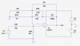
What you propose is to modify the circuit as in the following figure. Is that correct?
Attachments
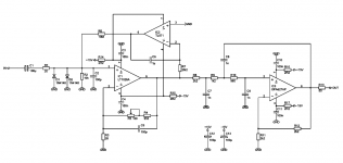
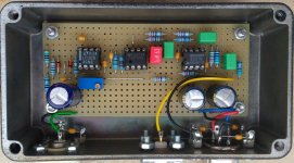
Here's what I built a few years ago for more or less the same purpose. Input noise voltage density is ~ 1.5nV/sqrt(Hz). By the way: For low frequency noise the LT1028 (~1nV/sqrt(Hz) @ 10Hz) is much better than the AD797 (~1.8nV/sqrt(Hz) @ 10Hz).
This is my third (and last) attempt to post this message including the images …
This is my third (and last) attempt to post this message including the images …
Attachments
Correct, with R5 = 113R or 110R (or no R5 and R34 = 9.20R, but that's an E192 (!) value). 100 ohms still isn't too bad though, that's 40.08 dB as-is and you might be perfectly happy with that. 110 ohms: 40.015 dB, 113 ohms: 39.9960 dB. The distinction between the last two may be pretty much moot unless you've got serious precision resistors (0.25% or 0.1%)...What you propose is to modify the circuit as in the following figure. Is that correct?
Here's what I built a few years ago for more or less the same purpose. Input noise voltage density is ~ 1.5nV/sqrt(Hz). By the way: For low frequency noise the LT1028 (~1nV/sqrt(Hz) @ 10Hz) is much better than the AD797 (~1.8nV/sqrt(Hz) @ 10Hz).
This is my third (and last) attempt to post this message including the images …
Your circuit is nice, close to what I am doing.
Yes, the LT1028 has lower noise than the AD797 below 100 Hz. I had not noticed that. Also the LT1028 is cheaper.
Thanks for this. I will order a LT1028 to make some measurements.
Here's what I built a few years ago for more or less the same purpose. Input noise voltage density is ~ 1.5nV/sqrt(Hz). By the way: For low frequency noise the LT1028 (~1nV/sqrt(Hz) @ 10Hz) is much better than the AD797 (~1.8nV/sqrt(Hz) @ 10Hz).
This is my third (and last) attempt to post this message including the images …
A servo. Nice.
Jan
Correct, with R5 = 113R or 110R (or no R5 and R34 = 9.20R, but that's an E192 (!) value). 100 ohms still isn't too bad though, that's 40.08 dB as-is and you might be perfectly happy with that. 110 ohms: 40.015 dB, 113 ohms: 39.9960 dB. The distinction between the last two may be pretty much moot unless you've got serious precision resistors (0.25% or 0.1%)...
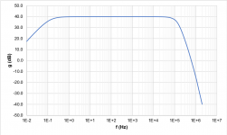
LTspice simulation shows that with R5=100, the gain is 40.007 dB.
With R5=113, the gain is 39.917 dB.
Also the output offset voltage of this circuit, again according to LTspice, is -3.24 Vdc (worst case).
- Status
- This old topic is closed. If you want to reopen this topic, contact a moderator using the "Report Post" button.
- Home
- Source & Line
- Analog Line Level
- AD797 offset null circuit