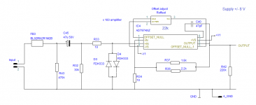
I have built a x100 Gain pre-amplifier using the AD797 opamp as shown below.
I have included a trimmer to null the output offfset as shown in fig. 55 of the datasheet.
The problem is that the output offset does not null but goes from +0.15V to +0.9V
Has someone else tried a similar offset null circuit with AD797 ?
Any suggestions ?
I have included a trimmer to null the output offfset as shown in fig. 55 of the datasheet.
The problem is that the output offset does not null but goes from +0.15V to +0.9V
Has someone else tried a similar offset null circuit with AD797 ?
Any suggestions ?
Attachments
I think the problem is that you are trying to trim offset errors caused by inappropriate circuit design/component values... remember the offset null adjustment is to null internal errors within the chip, not outside influenced design issues.
Your 30k input bias resistor is generating a relatively large DC voltage at the + input, the - input with its 10 ohm to ground generates essential no voltage at this node.
You either need to choose a more suitable opamp (very low input bias current) or redesign the circuit... or add coupling caps as Jon suggests.
The 20k value for the nulling trimmer is for +/-15V supplies, you use +/-8V supply so 10k trimmer is required. Well that's my take, it presumably is a current injection nulling system.
However the large imbalance in dc resistances to the two inputs is probably the dominant factor.
BTW a gain of 100 in one opamp stage might lower your bandwidth and increase distortion too much, much better to limit gain in each stage to 10 or thereabouts. Two x10 stages cascaded outperforms one x100 stage is most respects except power consumption.
To improve noise performance a x20 followed by x5 stage is perhaps optimal here, since extra front-end gain usually prevents later stages from contributing significant noise.
Last edited:
Why not just fit a 220u capacitor in series with R34 as the DC is blocked with C45.
Or add an output DC blocking cap in fact? The 10 ohm impedance of R34 is going to require a really big DC blocker value to avoid restricting LF gain.
I have built a x100 Gain pre-amplifier using the AD797 opamp as shown below.
I have included a trimmer to null the output offfset as shown in fig. 55 of the datasheet.
The problem is that the output offset does not null but goes from +0.15V to +0.9V
Has someone else tried a similar offset null circuit with AD797 ?
Any suggestions ?
Referencing your inverting input to ground with such a low value (10 ohms) is likely to unbalance the inputs in the op-amp somewhat. If your power supplies are not exactly equal you will end up with an output offset you can't null out.
Try upping the values of the parts in your feedback loop by, I would guess, a factor of at least 5 or maybe 10. You could also try adding a cap between R34 and ground so that the feedback chain can bias your input for you automatically.
Why not just fit a 220u capacitor in series with R34 as the DC is blocked with C45.
I want to use this circuit for measurement of very low level noise at the low frequencies, so a capacitor of 16000 uF will be needed in series with 10 Ohm for a -3dB frequency at 1 Hz. Not very practical.
I think the problem is that you are trying to trim offset errors caused by inappropriate circuit design/component values... remember the offset null adjustment is to null internal errors within the chip, not outside influenced design issues.
Your 30k input bias resistor is generating a relatively large DC voltage at the + input, the - input with its 10 ohm to ground generates essential no voltage at this node.
You either need to choose a more suitable opamp (very low input bias current) or redesign the circuit... or add coupling caps as Jon suggests.
Good points. It will be good to reduce the value of R at input to 10k.
I want to use this circuit for measurement of very low level noise at the low frequencies, so a capacitor of 16000 uF will be needed in series with 10 Ohm for a -3dB frequency at 1 Hz. Not very practical.
Does an output offset really matter? Noise is measured over a bandwidth, the average can be subtracted out.
Does an output offset really matter? Noise is measured over a bandwidth, the average can be subtracted out.
Yes, a 0.5 V offset doesn't matter at all.
I can put a 470uf at the output and the problem is solved.
I want to understand how the offset null circuit operates in the AD797, that is why I asked.
As mentioned before, the offset null is meant to null the internal offset, not to null out DC inputs. Because of the large difference in input R at DC, the input bias currents (which are nominally equal) generate a large DC input difference. If it was quite small you probably could null it with the offset pot but here it is too large. Fix the problem where it is: unequal DC input R.
You can use coupling caps but the problem will then remain and eat into your dynamic range.
Jan
You can use coupling caps but the problem will then remain and eat into your dynamic range.
Jan
But the problem is not the opamp, the problem is the circuit. If you have that 10 ohms in the feedback arm to ground, and 10k on the non-inverting input to ground, that generates the offset.
If you add a 10k between the inverting input and the top of that 10 ohms R34, it's fixed. Make R32 10k. You'll probably find you don't need the offset trimmer.
R33 should be 100 ohms to be useful as a stopper.
And D3 and D4 are in the wrong position. They should be between inverting and non-inverting input pins, not to ground.
Jan
Last edited:
Use a simple integrator (a TL071 is good enough for this purpose) to null the output offset. I'd also reduce R32 to 10k and inject the output of the integrator over a 10Meg resistor into R32.Any suggestions ?
But the problem is not the opamp, the problem is the circuit. If you have that 10 ohms in the feedback arm to ground, and 10k on the non-inverting input to ground, that generates the offset.
If you add a 10k between the inverting input and the top of that 10 ohms R34, it's fixed. Make R32 10k. You'll probably find you don't need the offset trimmer.
R33 should be 100 ohms to be useful as a stopper.
And D3 and D4 are in the wrong position. They should be between inverting and non-inverting input pins, not to ground.
Jan
Jan,
My purpose is to use this circuit as a very low noise amplifier with maximum input level at 20 mV.
If I add this 10k resistor between the inverting input and the top of 10 Ω, I agree that the offfset is reduced.
Actually, LTspice indicates that a 15 kΩ is better and reduce the offset to 2.6 mV! Amazing!
But my concern with the addition of this resistor is that will increase the noise. What do you think?
Concerning the stopper resistor 10 Ω, it has such a low value because I want to minimise its noise.
And the position of the diodes, I think it doesn't matter because of the 20 mV maximum input level.
regards
George
… and it's going to be very noisy. You don't need a AD797 (or a LT1028, which I would prefer for this purpose) for the noise performance (10k has 12.6 nV/sqrt(Hz) voltage noise density) you would get with a 10k resistor. Of course, this kind of amplifier is only low noise with a very low source impedance ...If you add a 10k between the inverting input and the top of that 10 ohms R34, it's fixed.
Jan,
My purpose is to use this circuit as a very low noise amplifier with maximum input level at 20 mV.
If I add this 10k resistor between the inverting input and the top of 10 Ω, I agree that the offfset is reduced.
Actually, LTspice indicates that a 15 kΩ is better and reduce the offset to 2.6 mV! Amazing!
But my concern with the addition of this resistor is that will increase the noise. What do you think?
Concerning the stopper resistor 10 Ω, it has such a low value because I want to minimise its noise.
And the position of the diodes, I think it doesn't matter because of the 20 mV maximum input level.
regards
George
OK, the reduce those resistors to 1k. And add an input buffer if the source can't cope with 1k.
The stopper noise at 100R will still be insignificant against (say) a 1k feedback/input R.
Diodes DO conduct at 20mV. If you want low distortion as well, do it the right way. It doesn't cost more to do it right instead of sloppy.
What sort of noise level are you looking for, what is the source and it's noise level?
Jan
VLF? What frequency do you think 47u and 30k roll off at? Certainly not 1HZ.I want to use this circuit for measurement of very low level noise at the low frequencies, so a capacitor of 16000 uF will be needed in series with 10 Ohm for a -3dB frequency at 1 Hz. Not very practical.
- Status
- This old topic is closed. If you want to reopen this topic, contact a moderator using the "Report Post" button.
- Home
- Source & Line
- Analog Line Level
- AD797 offset null circuit