Hi everyone.
Is this schematic (from a car amplifier but I want to implement this feature in a home preamp), the filter, a crossover? So the HPF signal is what's missing from the LPF one in the exact way as a proper crossover?

Looking at this Rod Elliot's crossover it seems to be the same thing...is it? So if it is the same thing I guess I could use it as such running the LPF + HPF signals without problem and with the same performance as the Elliot's crossover right? Or if I wanted the LPF + FLAT signal too without problems?
Another question is that as I will use one or the other as base because both lack features, from the other and in general, could I simply add the feature the other lacks? For example the FLAT of the car amp in Elliot's crossover, or the 11.2K R2 resistor in Elliot's one that controls the Q value in the other one, or what I guess is a "differential balanced output" from the car amp in the Elliot's before the crossover, etc?
What if I add somewhere a baxandall tone control?, in the FLAT signal or before the crossover? Or a sort of parametric eq (some car amps has this just after what the schematic show but only boosting and not cutting).
Thanks
Is this schematic (from a car amplifier but I want to implement this feature in a home preamp), the filter, a crossover? So the HPF signal is what's missing from the LPF one in the exact way as a proper crossover?
Looking at this Rod Elliot's crossover it seems to be the same thing...is it? So if it is the same thing I guess I could use it as such running the LPF + HPF signals without problem and with the same performance as the Elliot's crossover right? Or if I wanted the LPF + FLAT signal too without problems?
Another question is that as I will use one or the other as base because both lack features, from the other and in general, could I simply add the feature the other lacks? For example the FLAT of the car amp in Elliot's crossover, or the 11.2K R2 resistor in Elliot's one that controls the Q value in the other one, or what I guess is a "differential balanced output" from the car amp in the Elliot's before the crossover, etc?
What if I add somewhere a baxandall tone control?, in the FLAT signal or before the crossover? Or a sort of parametric eq (some car amps has this just after what the schematic show but only boosting and not cutting).
Thanks

These are (2nd order) state variable filters, a common way to get high pass, band pass and low pass simultaneously. Yes, you can use this as a cross-over.
So the sum of both is a rather flat result right? And not an improper mess with a peak or a dip in the middle?
P148 has an additional inverter on one of the outputs, you'd probably need that.
Be warned that the car audio circuit has its quirks. It seems the resistor values may have been originally chosen for a TL072 or similar and are not at all optimized for a low-noise bipolar opamp like the NJM2068. The flat amp stage right after input level control is screwing up output noise levels, I would change it to noninverting with resistor values at least a decade lower than now (e.g. Rf=4k7 / Rg=820R, and a couple hundred ohms in series + 47k bias on the noninverting input).
So maybe taking the ESP circuit and adding the two preceding stages would be an idea.
Having the balanced input is neat (definitely not a bad idea in car audio), but again 47k resistors are a tad on the high side - I'd suggest 22k or 10k.
If you already have a balanced receiver, you might as well add some actual balanced inputs as well - e.g. XLR. If you have 10k/10k for the RCA, I'd suggest adding XLR via 22k to 39k (i.e. circuit config = 22k...39k / 10k when using XLR, 10k / 10k on RCA). XLR pin 1 goes to chassis.
A Baxandall tone control would definitely go ahead of the actual state variable crossover, e.g. after flat amp.
Last edited:
P148 has an additional inverter on one of the outputs, you'd probably need that.
Be warned that the car audio circuit has its quirks. It seems the resistor values may have been originally chosen for a TL072 or similar and are not at all optimized for a low-noise bipolar opamp like the NJM2068. The flat amp stage right after input level control is screwing up output noise levels, I would change it to noninverting with resistor values at least a decade lower than now (e.g. Rf=4k7 / Rg=820R, and a couple hundred ohms in series + 47k bias on the noninverting input).
So maybe taking the ESP circuit and adding the two preceding stages would be an idea.
Having the balanced input is neat (definitely not a bad idea in car audio), but again 47k resistors are a tad on the high side - I'd suggest 22k or 10k.
If you already have a balanced receiver, you might as well add some actual balanced inputs as well - e.g. XLR. If you have 10k/10k for the RCA, I'd suggest adding XLR via 22k to 39k (i.e. circuit config = 22k...39k / 10k when using XLR, 10k / 10k on RCA). XLR pin 1 goes to chassis.
A Baxandall tone control would definitely go ahead of the actual state variable crossover, e.g. after flat amp.
Thanks for all that!
As I knew there were variations in the schematics I have, even if all of them follow the same style, I started looking at them with what you said in mind and look at this one, it has changes in line with all your advices!:

As far as I can see now it's only missing the AUX output wich I guess it can be added easily, right?
But what I'm not sure is where the signal is going in that input, as this other is going to the non-inverting, while the original was in the inverting and they look the same.

I guess is going to the inverting input as there's a capacitor to ground, but while in the other two the cap is a 1nF, in this is a 220uF!!! Why such difference??
Also that FL1 (with RJ45 GND) don't know what that is...
And that transistor at the end...What changes should I make on that part?
(I know I probably should just use the Elliot one with the preceding stages as you say, it's just that as the Elliots doesn't have the 3 outputs, and I need those...)
And about that input, I really don't understand it: is it the one called "differential balanced input"? But does it need a balanced source (I don't have)? My idea is to use it with a smartphone for example or an old CD player, bluetooth dongle, soundcar output (for Hi Res), etc.
Last edited:
Well, you definitely overdid it there. You do know that the LM833 is only an average load driver? Also, beware: TI sells two LM833 variations these days, one the original NatSemi part (called "LM833-N", LM833N in DIP), one their own take on the MC33078 (LM833P in DIP).Thanks for all that!
As I knew there were variations in the schematics I have, even if all of them follow the same style, I started looking at them with what you said in mind and look at this one, it has changes in line with all your advices!:
View attachment 788244
R101A is used to limit level adjustment range, why did you change that (unless that is precisely what you set out to do)?
R102A at 2k7 is too low in relation to the output impedance of a 20k pot (~5k max). Or did you want to "fake log" a linear pot?
R103A/R110A @ 1k8/100R is lower than needed - when the input voltage noise of your opamp is about the equivalent of 1 kOhm, you don't have to go as low as 100R externally. And why this much gain anyway, wasn't it 9 or 10 dB less before? That'll bring the noise output of this stage right back up!
R115A/R117A at 1k/1k: No, why? Think of the poor opamps that have to drive this. A 4558 won't like this too much, and the LM833 won't be entirely happy either. And what for anyway? The crossover and gain stage are going to be more noisy for sure. You could use 10k and it wouldn't matter much (noise output ~3 µV, vs. gain stage with LM833 at 4k7/820R: >6 µV).
R116A: I don't know why that is even there is the first place, it merely increases noise gain. Could be used to tame an opamp at less than minimum stable gain, but I don't see the point here.
Since you need all 3 outputs, you may have to duplicate the output buffer.
Seems like you could use an opamp noise calculcator. Here is the one I use.
You should also start doing some sort of level planning. Particularly, how much output level and how much output noise you are going to need. If you have both a flat amp and an (inverting) output amp, you can pretty much shift levels in the crossover around, so you can find a good compromise between noise and distortion performance. What are you planning to follow this up with? You'll need some level adjustment for your drivers, and you can have a lot of fun with output noise when using high-sensitivity drivers.
Indeed.As far as I can see now it's only missing the AUX output wich I guess it can be added easily, right?
The first circuit had a noninverting input stage and inverting gain stage.But what I'm not sure is where the signal is going in that input, as this other is going to the non-inverting, while the original was in the inverting and they look the same.
View attachment 788245
This one has an inverting input stage and noninverting gain stage.
Both are giving the same absolute phase. Since inverting phase on a balanced input is trivial (swap the inputs around), you can do so as needed.
I have no idea what you are talking about here. Mind marking these components on the schematic?I guess is going to the inverting input as there's a capacitor to ground, but while in the other two the cap is a 1nF, in this is a 220uF!!! Why such difference??
Also that FL1 (with RJ45 GND) don't know what that is...
This looks like some sort of attenuator and wouldn't be doing very much with the values shown. Do you even need that functionality?And that transistor at the end...What changes should I make on that part?
I don't see what the problem is. Don't you effectively have all your 3 outputs available once you've added the flat amp stage?(I know I probably should just use the Elliot one with the preceding stages as you say, it's just that as the Elliots doesn't have the 3 outputs, and I need those...)
Yes, it's a balanced input, and no, it doesn't need a balanced output. It won't deliver perfect CMRR with unbalanced source impedance (which may have been part of why they went with 47k resistors originally), but it'll be a whole lot better than a plain unbalanced input still, plus your sources would generally have low(ish) output impedance anyway. Remember this is a car audio device, and cars have all kinds of nasty ground currents running around, plus everything is fed from the same DC power source and grounded to the same chassis.And about that input, I really don't understand it: is it the one called "differential balanced input"? But does it need a balanced source (I don't have)? My idea is to use it with a smartphone for example or an old CD player, bluetooth dongle, soundcar output (for Hi Res), etc.
One or two of the buses I am riding around here clearly did not have that much thought put into their PA systems, as you'll have plainly audible whining and whistling whenever the system unmutes to make an automatic station announcement. That's what happens when you get a ground loop in a car.
Your home may not be as electrically hostile as a motor vehicle, but let me tell you, it still is really easy to get into trouble with ground loops. A lot of perople will build their DIY power amps as IEC Class I devices, i.e. audio ground ultimately connects to protective earth, often "hard" (directly). Well, guess what your PC will do, just the same. Connect both, and you'll get a first-rate ground loop. Then you'll have to bust out your audio isolation transformers - or have a balanced input.
There are various ways of further improving balanced input performance, BTW:
1. Add unity gain buffers up front in each leg, which allows you to have high input impedance regardless of resistor values in the bal/unbal stage (so you could easily go down to 4k7s or even 3k3s there for lower noise).
2. Most buffered inputs like that would just have 100k bias resistors to ground. A more clever version: 10k + 10k from each leg meeting, then going via 100k to ground. (Similar if you need higher input capacitance, you could have e.g. 1n + 1n and then 100p to ground. An additional 47-100p from each leg to ground right at the input is recommended.) This more than doubles common-mode input impedance (for better CMRR in the face of mismatched source impedance) while keeping differential input impedance reasonably low (for less noise and "antenna effect" with the input open). You can even go higher than 100k for the common resistor, as any voltage appearing over it from opamp input current is purely common-mode and hence suppressed by CMRR.
3. Turning an unbalanced input into a (decent enough) balanced one is quite trivial as long as you know what's behind it: You just need to replicate the output impedance on the "signal" side in the connection to the "ground" side. Lots of home studio equipment actually does it like this - if they have 100 ohms and 22 µF in series with the signal output for "+out", they'll add another 100 ohms and 22 µF to ground for "-out". Of course this means that the balanced receiver will see a signal that is partially common-mode, and its distortion performance may suffer if its common-mode linearity is not good, but for rejection of ground loop noise this is irrelevant.
Rod Eliott has several articles on balanced connections, these may be a good read.
Well, you definitely overdid it there.
No, it's just another schematic I found that it seemed to follow what you were saying. So none of that is my work and no intentions there either, of course.
But are those that bad? I assumed that as they were car amplifiers, where sound quality isn't precisely appreciated or even needed, they wouldn't be very good...but that bad?!
I only know very very basic stuff. I do my projects mostly by copying from good sources and hoping they work. And up until now all but one of the many things I did worked. How good, not sure, but worked apparently as intended.
I'm going to do this: tomorrow I will make a block diagram of what I want, post it here and you tell me your thoughts (if ou want of course).
You do know that the LM833 is only an average load driver? Also, beware: TI sells two LM833 variations these days, one the original NatSemi part (called "LM833-N", LM833N in DIP), one their own take on the MC33078 (LM833P in DIP).
I was planning to replace them with NE5532 that are supposedly the same chip, although today I saw there was a difference in the bipolar input transistor...no idea.
I have no idea what you are talking about here. Mind marking these components on the schematic?
I can't mark those components now but the capacitors I'm talking about are the ones from signal to ground in the input (C101/C201), that capacitor is 1nF in the other schematics and 220uF on this one.
FL1/FR1 is that just under it.
I don't see what the problem is. Don't you effectively have all your 3 outputs available once you've added the flat amp stage?
The problem is all it lacks. But if it's easier to add to the Elliot's one what it doesn't have than rectify all the problems with the 5350a that is basically complete...Thing is, due to my insufficient kowledge, I'm not sure if I can do it, so I was "hoping" that one of these car amplifiers preamp stages would do...but as I said they seem to be even worse than I expected!
Your home may not be as electrically hostile as a motor vehicle, but let me tell you, it still is really easy to get into trouble with ground loops.
I "live" next to a radio antenna. I made this other thread asking precisely about this project, and one of the things in the thing I was thinking on copy there
") D) were the common mode chokes because of the antenna problem. And I recently read that this car amp's balanced inputs could be useful as well...but I still don't know...
D) were the common mode chokes because of the antenna problem. And I recently read that this car amp's balanced inputs could be useful as well...but I still don't know...I will also read again more carefully all you written, I appreciate a lot all the info. Will post tomorrow the block diagram of my plan here (or on the other thread if you prefer).

Sounds good.I'm going to do this: tomorrow I will make a block diagram of what I want, post it here and you tell me your thoughts (if ou want of course).
They are definitely not the same chip, they just belong to the same class - the first wave of low noise, low distortion bipolar audio opamps from the 1980s. LM833 and MC33078 were lower-cost alternatives to NE5532. Samuel Groner has measured all 3. TI's NE5532 can actually be worse in low/unity gain noninverting stages than the alternatives due to its comparatively bad common-mode linearity (as evidenced by the high frequency linearity test), but other manufacturers' ones seem to be better in this respect.I was planning to replace them with NE5532 that are supposedly the same chip, although today I saw there was a difference in the bipolar input transistor...no idea.
Ah. With the 220µ cap, no idea what they were thinking there. This usually is just for shunting RF, it makes absolutely no sense to be using a cap that large, as it would eliminate pretty much any benefits of the balanced input stage. (Even so, having the 1n capacitor only on one leg throws off balance at higher frequencies.)I can't mark those components now but the capacitors I'm talking about are the ones from signal to ground in the input (C101/C201), that capacitor is 1nF in the other schematics and 220uF on this one.
FL1/FR1 is that just under it.
FLI/FRI appear to be just additional / alternative inputs, coming from somewhere via twisted pair cabling if the "RJ45" is any indication.
I mean, the basic topology isn't bad, I just don't agree with all component values.The problem is all it lacks. But if it's easier to add to the Elliot's one what it doesn't have than rectify all the problems with the 5350a that is basically complete...Thing is, due to my insufficient kowledge, I'm not sure if I can do it, so I was "hoping" that one of these car amplifiers preamp stages would do...but as I said they seem to be even worse than I expected!
BTW, when seeing the schematic that had NJM2058 marked on it, the penny finally dropped. Those are quad 4558s, and they are not substantially better at load driving than TL07x, and not all that low noise either. That explains the highish impedances.
Why then they went with NJM2068s when they needed duals, no idea. Maybe those weren't much more expensive than other alternatives in SIP-8. (It's one of the few interesting parts you can get in that oldschool package, alongside NJM4556A, NJM5532, NJM2114 and maybe the NJM4565 if you need a low-Ib part. Oh, the NJM2114 seems to have gone EOL recently. That was JRC's "super 5532" - never got all that popular it seems, even though it did make an appearance in higher-end soundcards from both Creative/EMU and Asus.)
Balanced inputs tend to be a good idea regardless of whether you are living next to an AM flamethrower or not. Some extra attention is likely to be required in your scenario. A common-mode choke between the 47-100p to ground at the input and the T'd larger caps + bias Rs is likely to be a good idea, as well as a few hundred ohms in series in each leg...I "live" next to a radio antenna. I made this other thread asking precisely about this project, and one of the things in the thing I was thinking on copy there
BTW, when you talk about "copying", you are basically talking about coming up with your own layout, are you? As they say, the layout is the circuit, and there still is enough to go wrong there...
So the sum of both is a rather flat result right? And not an improper mess with a peak or a dip in the middle?
The sum of all three (suitably phased/scaled) is exactly the input, that's how the circuit works. Sum high and low and you get a notch filter.
That was JRC's "super 5532" - never got all that popular it seems, even though it did make an appearance in higher-end soundcards from both Creative/EMU and Asus.)
Really? Didn't remember that. But here I never could get any NJM model in my hands...or an OPA or a high end LM, only the old basic opamps/ TL07x/LF35x/NE5532/RC4558/LM833/TL741 probably some other). I can order them but I have to buy tens of them or more in dolar price, wait many days when I just casually need 2 or 4 and just for testing or a small personal project...
Balanced inputs tend to be a good idea regardless of whether you are living next to an AM flamethrower or not. Some extra attention is likely to be required in your scenario. A common-mode choke between the 47-100p to ground at the input and the T'd larger caps + bias Rs is likely to be a good idea, as well as a few hundred ohms in series in each leg...
I would need a schematic of that. In the other thread I posted this input schematic of the Edifier C200 and it have the commom mode choke in front of the first op amp

I have a small toroidal core form another choke that I could turn into one of those, it's just a bit smaller than the ones in the C200.
BTW, when you talk about "copying", you are basically talking about coming up with your own layout, are you? As they say, the layout is the circuit, and there still is enough to go wrong there...
Yeah I know, but I still feel like cheating...in my opinion, I know I am!
I'm doing the block diagram of my idea, in some minutes I'll post it here.
The sum of all three (suitably phased/scaled) is exactly the input, that's how the circuit works. Sum high and low and you get a notch filter.
Yes, yes, but my question was more about an anomaly on the expected flat result, like a dip or a peak because of a possible improper design.
Sounds good.
HA! Took me more than a few minutes...dammit...but here it is:

Should be simpler than that, so probably I will get rid of some parts, some functionalities that probably will never be used...
There are that many aux outputs and not so many switches because here multiple poles switches are almost impossible to get (I know they are hard to get everywhere but here it's worse).
The bluetooth module part is bassically the circuit being prepared for adding one of those and/or something else.
The power supply is one of those multiple voltage, cheap 96 Watts universal notebook chargers (yeah...another problem...but this C200 is powered by an internal switching PS and works perfectly).
Planning to make a subwoofer amp too, in the not so distant future...
You are most likely to find them in Japanese and other Southeast Asian audio equipment. (NEC opamps may be even more exotic.) I guess the most popular JRC opamps would have to be:Really? Didn't remember that. But here I never could get any NJM model in my hands...or an OPA or a high end LM, only the old basic opamps/ TL07x/LF35x/NE5532/RC4558/LM833/TL741 probably some other). I can order them but I have to buy tens of them or more in dolar price, wait many days when I just casually need 2 or 4 and just for testing or a small personal project...
NJM4580 (rather universal, quite low voltage noise, decent output driving, more LM833/MC33078 competition basically but less noisy)
NJM2068 (low voltage noise, good GBW, so-so output driving, Yamaha used those by the bucketload at some point)
NJM4556A (the first dedicated headphone amplifier, and still useful in this function today)
The O2 (DIY) headphone amplifier designed by one NwAvGuy used the latter two parts to make a point - that it doesn't take fancy expensive parts to make something that performs very well for the vast majority of people (well, except for the owners of certain planar headphones or vintage 600 ohm AKGs perhaps). He measured performance of a few opamps, too.
Just one? Well, I suppose since the inductance of a common-mode choke cancels out for differential-mode signals, so should any coupling between the two. So you could probably wind 2 pairs of wires on there, or even more, space permitting.I would need a schematic of that. In the other thread I posted this input schematic of the Edifier C200 and it have the commom mode choke in front of the first op amp
View attachment 788832
I have a small toroidal core form another choke that I could turn into one of those, it's just a bit smaller than the ones in the C200.
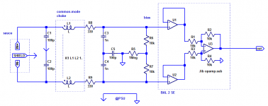
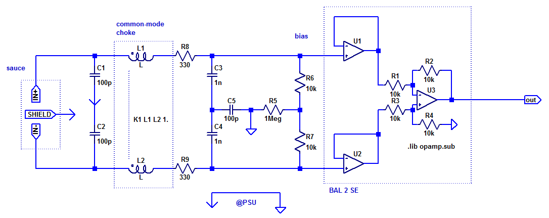
Here's what I had in mind:
I used two types of ground symbols (COM and GND) to differentiate between chassis ground and circuit ground. A balanced (e.g. +/-15 V) power supply is assumed. Hand-matching of critical resistors R1-4 strongly advised, and it's not a bad idea for any other components that occur in pairs in both legs. Maximum input amplitude is determined by U1/U2 input common-mode range at given supply voltages. A standard balanced input with shield connection is shown, you will need IN+ and IN- only.
Take it as a starting point. More components may be required for RF proofing, and R1-4 can be optimized according to the abilities of U1-U3.
The layout should not look like the circuit is drawn, but rather both legs should be kept closely together. Not a bad idea for e.g. supplies V+/V- either.
I'm doing the block diagram of my idea, in some minutes I'll post it here.
So what you want is not that exotic, really.
Just one major change that I would suggest:
I would move the tone control between source selection and crossover input.
a) This makes its noise essentially irrelevant, and any old Baxandall with 50k or 100k pots and NE5532 would work perfectly fine. OK, you do want film capacitors rather than ceramics in the Baxandall.
b) It also means that the tone control's absolute phase is irrelevant and can't mess up sub/main XO.
Speaking of absolute phase, it would be really nice to have at least a choice of normal and inverting on the sub output. Subs of the better kind tend to include an analog phase shift control. Not sure how that works, possibly some sort of variable allpass.
I would leave crossover frequency variable for better flexibility, though you would probably get along fine with a reduced range (up to about 150 Hz is likely to do just fine).
The input level control in the crossover could serve as a main volume control.
If you want to use an off-the-shelf headphone amp, best tap off after input selector.
You can have a lot of fun with the grounding if you want to supply both the crossover and the tone control and maybe something else from the same power supply... at AF and RF.
I would suggest studying some of Bruno Putzeys whitepapers... especially "The G Word" and the one on legacy pun 1 problems.
Hypex Electronics B.V.
There are that many aux outputs and not so many switches because here multiple poles switches are almost impossible to get (I know they are hard to get everywhere but here it's worse).
You could always make a binary tree of switches, just like a relay-based input selector. (So the last one selects between groups A and B, and then 2 more between A1/A2 and B1/B2, etc.) I hope you can get some DPDTs at least? What about 4PDT?
The crux of switching balanced inputs is needing twice as many switch contacts. On the plus side, you do not have to connect the grounds of all your sources then, avoiding potential ground loops between them. Having one balanced receiver circuit per input isn't a particularly enticing prospect either.
Maybe you can get the good ol' CD4052B multiplexer IC? I mean, it's only good to 20 V tops (so e.g. +/-9 V) but might make this whole ordeal a bit easier or at least more feasible. I might put it between the input filtering and the bias resistors. (Knowing CMOS circuits and their propensity to being fried, the 330R resistors may also be worth resizing to 1k or even 2k2, matched.)
You will have to keep distortion due to r_ON nonlinearity at bay (see datasheet) - this basically means making (source + load) impedance as high as possible to keep r_ON negligible. I'll suggest upsizing R6/R7 to 100k and just adding another 22k across IN+ and IN- at the input filter... going capacitor-coupled at the input and connecting bias R5 to a low-noise ca. +1.25 Vdc also seems worth a shot. (10k to -9V, 7k5 to +9V, 10µF to ground, sounds good to me.)
Maybe even better, keep the circuit up to and including U1/U2 as originally suggested and ahead of the 4053 (alas, replicated for each input - so you basically need a cheap dual opamp with rather good common-mode linearity and decent slew rate but without major driving abilities; maybe this is the MC33078's or LM833's time to shine? Or even the LM837 quad, though that is notorious for its low phase margin and hence lack of stability near unity gain). This will protect the 4053 from being zapped quite effectively. After the 4053 you put in another set of unity-gain buffers with standard 100k-220k to ground (or rather +1.25 V) buffering before following that up with U3/R1-4 again. I would even be tempted to bootstrap the input bias to get super high input impedance. (I'll have to draw that for you, don't I?)
Silly me, you don't even explicitly have to generate +1.25 V and AC-couple the input, you might as well use e.g. a +7.5 V / -10 V supply. (If a 79M10 regulator is too exotic for your tastes, there's always the old trick of using 1-2 diodes in series with the ground connection to bring up the voltage on a more common 9 V part.) +8V/-12 V would be on the limits of this part but quite common types. If in doubt one could always use an adjustable regulator circuit e.g. with LM317/337. Or maybe you wanted some RC filtering after the regs anyway...
How much does this thing normally cost? The one off-brand charger I've come across that actually seemed half-decent was such a multivoltage job.The power supply is one of those multiple voltage, cheap 96 Watts universal notebook chargers (yeah...another problem...but this C200 is powered by an internal switching PS and works perfectly).
Being 96 W, it pretty much has to have a 3-prong power receptacle, like an IEC of some sort. How does it connect protective earth and secondary-side ground? Directly, or any R and/or C?
Generic knockoff (counterfeit "original") chargers can be outright terrible... nonexistant mains power filtering ... nonexistant cable strain relief.... bad parts quality... heat not transferred to outside case efficiently... the list goes on.
SMPS definitely are not all made alike! I'd prefer one of these metal case jobs for internal use, ideally one that gives you a way to control how to hook up the mains filter - so you should have L, N, PE terminals as well as OUT+ and OUT-. Compliance with common safety regulations is not something I would consider optional.
Do you have your eyes set on a matching case for the whole stuff already?
You are most likely to find them in Japanese and other Southeast Asian audio equipment. (NEC opamps may be even more exotic.) I guess the most popular JRC opamps would have to be:
NJM4580 (rather universal, quite low voltage noise, decent output driving, more LM833/MC33078 competition basically but less noisy)
NJM2068 (low voltage noise, good GBW, so-so output driving, Yamaha used those by the bucketload at some point)
NJM4556A (the first dedicated headphone amplifier, and still useful in this function today)
I will have to go and see what I can find. I think the RC4558 and NE5532 will be enough, no need to go high end on this thing.
Ha! My now broken X-Fi Xtreme Music had the JRC4556:

The O2 (DIY) headphone amplifier designed by one NwAvGuy used the latter two parts to make a point - that it doesn't take fancy expensive parts to make something that performs very well for the vast majority of people (well, except for the owners of certain planar headphones or vintage 600 ohm AKGs perhaps). He measured performance of a few opamps, too.
Oh see? No need for super high end, especially given It will take time to find good enough speakers (I stupidly lost the chance to buy an used 3 way speaker with a planar ribbon tweeter and dome mids for almost nothing, I will never stop kicking myself over that!)
Just one? Well, I suppose since the inductance of a common-mode choke cancels out for differential-mode signals, so should any coupling between the two. So you could probably wind 2 pairs of wires on there, or even more, space permitting.
I had only one lying around but I knew there were more, I just found 2 more, 2 alike and one slighty different, all very small.

The C200 have 1 per input running the 3 poles in parallel: left, right, ground.


It will be great to do mine with the coils, and if I have to sell one to somebody, use the differential balanced instead, right?
Here's what I had in mind:

Aaahh the link doesn't work!
So what you want is not that exotic, really.
It shouldn't be, but actually I never see something like this, and it's not so complicated either. Seriously, things like this should be common but DIYers and companies insist on make either super cheap, super simple or super premium stuff and none with common or useful functionalities.
Just one major change that I would suggest:
I would move the tone control between source selection and crossover input.
a) This makes its noise essentially irrelevant, and any old Baxandall with 50k or 100k pots and NE5532 would work perfectly fine. OK, you do want film capacitors rather than ceramics in the Baxandall.
b) It also means that the tone control's absolute phase is irrelevant and can't mess up sub/main XO.
Yeah you told me that before, but where I put it made more sense as sub outputs aren't equalized (except with especial subwoofer controls that I originally wanted for my separated version of the crossover, a 1 to 3 bands parametric one) like that, and that the baxandall itself can make the headphones amp (I did this before with gain in the first opamp). But then one could simply return the baxandall to 0 and the gain would mess up the balance on outputs...although it wouldn't matter as they would go to different amps...Also will make the switching to amp easier as they are 2 (4) instead of 3 (6) poles to switch...Bleh!
The film capacitors I use to find here (I didn't buy any in about 2 years!) are the red and green ones, only once I got the grey box shaped ones. So, if those are ok, no problem.
About "b", not sure what you're saying. You mean the phase changes because of the tone control and crossover or the inverting? If the former, well, it's important.
Speaking of absolute phase, it would be really nice to have at least a choice of normal and inverting on the sub output. Subs of the better kind tend to include an analog phase shift control. Not sure how that works, possibly some sort of variable allpass.
Yes, good idea, didn't thought of that here because the crossover here it's just a way to further improve the functionality. But in my main crosoover project for my C200 yes it will have. I don't know how the phase shifting in subs work but knowing that "phase" is used in two different ways, "direction of waves" and "delay of a signal", given that it's usually a 0º to 180º knob rather than a 0 or 180 switch most of the times, and reading this
"The phase control operates over a range of 0 to 180 degrees. Adding delay to the subwoofer signal can sometimes help the subwoofer to integrate better with the loudspeakers in the room."
Then it says:
"All SVS subwoofers feature a continuously variable 0-180 phase control which allows the most complete range of adjustment in small increments to achieve the best sound possible. Other brands of subwoofers may only offer a simple 0/180 phase switch (also referred to as a polarity switch), which not as useful as a true variable phase control."
...then it's usually just delay, and I refuse such a thing! (and people in sound complain about real features that they call gimmicks! Amazing...). Now, this ones are real phase switching/inverting from old subwoofer schematics I have:


I would leave crossover frequency variable for better flexibility, though you would probably get along fine with a reduced range (up to about 150 Hz is likely to do just fine).
I would love to, but pots are F expensive here, and as I said limited functionality is fine. But given there will be only 2 dual gang pot (forget about finding a 4 gang one) probably will be variable...
Ok, that's it!! You pushed me enough! I'm going to make it more complete and possible to use it alone!
...but now makes even more sense to put the tone control out of the crossover path (especially becasue of the HPF/FLAT line out)...
The input level control in the crossover could serve as a main volume control.
Yes, I kept forgetting about this important part.
And before I forget, I think a gain/sensitivity switch will be good because of all the different sources with different power, some too weak, some too strong.
If you want to use an off-the-shelf headphone amp, best tap off after input selector.
Nah, the idea is either a simple opamp or not even that, and as I will need the baxandall tone, after this will be enough. It's just for normal headphones, not high impedance ones. And remember that the NE5532 can drive big loads...supposedly...
I made this thing years ago and drives normal headphones strongly:

You can have a lot of fun with the grounding if you want to supply both the crossover and the tone control and maybe something else from the same power supply... at AF and RF.
My fears. That and any other kind of noise and distortions due to PS (or bad desing).
And something I forgot to add to the black diagram. But yeah the original idea was to use the one PS filtering after it and use a single supply for the opamps to simplify (as I don't have to create a negative voltage from the single supply notebook charger). I know it works fine and the C200 has that. As it says in the other thread, the C200 has the switching PS +15v with it's filtering, goes to the board feeding the 7379 directly and the with the opamps, there's an SMD inducor or similar before a 7809 that feeds them in single ps mode.
But on the other hand all the shcematics have to be changed, a lot...So if there's a good proper way to turn a single PS into a dual ps (the 7379 will be fed from 16v to 18v).
I would suggest studying some of Bruno Putzeys whitepapers... especially "The G Word" and the one on legacy pun 1 problems.
Hypex Electronics B.V.
Thanks, will look.
You could always make a binary tree of switches, just like a relay-based input selector. (So the last one selects between groups A and B, and then 2 more between A1/A2 and B1/B2, etc.) I hope you can get some DPDTs at least? What about 4PDT?
Yes, I had that idea, but of course, don't wanted such a thing. Yes, DPDTs are no problem and I already have some. 4pdt no, impossible to get, but I will ask again.
The crux of switching balanced inputs is needing twice as many switch contacts. On the plus side, you do not have to connect the grounds of all your sources then, avoiding potential ground loops between them. Having one balanced receiver circuit per input isn't a particularly enticing prospect either.
Why? Aren't these kinds of "balanced" just as normal inputs, you know, with 2 poles, signal and ground?
Maybe you can get the good ol' CD4052B multiplexer IC?
I always wanted to do something with those, but don't wan't to complicate this that much. I need to keep this simpler.
(I'll have to draw that for you, don't I?)
But again, maybe I should not do it. It's cheaper and nicer than switches and mnultiple jacks but I prefer less compications, less board size, etc (also I would love to replace dual pots with digital solutions...oh yeah!!).
How much does this thing normally cost? The one off-brand charger I've come across that actually seemed half-decent was such a multivoltage job.
About 10 to 20 Us$. And they have good reviews. Now for audio...uncharted territory...
I bought it used and super cheap, that's why I already have it
Yes, 3 legs.Being 96 W, it pretty much has to have a 3-prong power receptacle,

like an IEC of some sort. How does it connect protective earth and secondary-side ground? Directly, or any R and/or C?
No idea.
Generic knockoff (counterfeit "original") chargers can be outright terrible... nonexistant mains power filtering ... nonexistant cable strain relief.... bad parts quality... heat not transferred to outside case efficiently... the list goes on.
Yes, and I expect nothing better! But it's the only PS I can afford for the moment so I have to make it work. Through heavy filtering I guess...a thing that needs coils...things hard to find here! So I have to use simple stuff.
Of course I could obtain a normal transformer, but they are absurdly expensive and the quality...
SMPS definitely are not all made alike! I'd prefer one of these metal case jobs for internal use, ideally one that gives you a way to control how to hook up the mains filter - so you should have L, N, PE terminals as well as OUT+ and OUT-. Compliance with common safety regulations is not something I would consider optional.
They sell those, but they are too expensive here.
Do you have your eyes set on a matching case for the whole stuff already?
Nah, I don't care about aesthetics. After I make the internals I will build one from some 1mm (or 1,5mm, don't remember) aluminum sheets I have, and/or wood. Or maybe I will get some metal case for racks...
------------------
If I put the baxandall before the crossover I could just go with this Elliot design, modify the input for RF filtering (balanced or the coil), remove the balance, add a gain switch maybe, etc.
Oh no. Fixed:Aaahh the link doesn't work!
The forum software has a habit of deleting what it thinks are "unused" attached images if you keep editing for a while after uploading them without posting yet. You don't immediately notice because you have done a preview and the browser has cached the image.
Attachments
Oh no. Fixed:
The forum software has a habit of deleting what it thinks are "unused" attached images if you keep editing for a while after uploading them without posting yet. You don't immediately notice because you have done a preview and the browser has cached the image.
Yeah I found out precisely when doing this thread...or was the other...? Well, one of them.
Your circuit confuses me too much! I'm really not sure what I'm seeing! Haha!
I mean it's very similar to the Edifier C200 near the input, but apparently balanced. Remember I don't need that.
Last edited:
I mean, XLR type balanced. It's a mistery to me.but apparently balanced. Remember I don't need that.
(Surely there's something here I'm not understanding, but I'm saying just in case
)Ufff!
Hey Sgrossklass, I made 4 schematics of most of the circuit.
I tried to make all the changes you proposed in earlier comments, but also did the baxandall in parallel version that you don't like, just to see if it's valid anyway.
Most sections were actually made separately for different reasons at different times, so I modified what I could register. The opamps models for example are mostly 4558 because that's what was at the original, you tell me which to change (I want to simply use 5532 and 4558).
Power supply is of course mostly missing as I still don't know how to solve that, you know: all from the charger, dual or single for opamps (prefer dual now so I don't have to modify everything)... (and the 7805 ad USB is for cellphone charging and to feed a cheap bluetooth audio dongle).
And well, it's very rudimentary and faulty etc. So if you can, tell me what's wrong.


The crossover section is from the PX600.2 and forgot to check it so it's as I originally drew it back then.
Some pots are pots and the volume are connectors, but you will realize that easily.
The baxandall is on from Elliot.
Inputs from Edifier C200 (as it's similar to your last drawing) and the car amplifiers
Amplifier section from C200 with some modifications from others (unused pins).
The Common mode choke are connectors too.
There's one 3.5mm at the end, near the TDA7379, and the rest are connectors, but that particulary should be the headphones output, I simply didn't "connected" yet.
And well, many other stuff that you will see weren't on purpose, etc.
Also there are some confusing stuff at the input, I added some "High level inputs/outputs" to use the crossover (you know if I'm going to make it variable, then I will make it useable...). I copy them from different subwoofers schematics...no idea what I'm doing there...as with the rest of the circuit ... well, tried to use some common sense and the very very little limited knowledge.
Awaiting your response!
Hey Sgrossklass, I made 4 schematics of most of the circuit.
I tried to make all the changes you proposed in earlier comments, but also did the baxandall in parallel version that you don't like, just to see if it's valid anyway.
Most sections were actually made separately for different reasons at different times, so I modified what I could register. The opamps models for example are mostly 4558 because that's what was at the original, you tell me which to change (I want to simply use 5532 and 4558).
Power supply is of course mostly missing as I still don't know how to solve that, you know: all from the charger, dual or single for opamps (prefer dual now so I don't have to modify everything)... (and the 7805 ad USB is for cellphone charging and to feed a cheap bluetooth audio dongle).
And well, it's very rudimentary and faulty etc. So if you can, tell me what's wrong.
The crossover section is from the PX600.2 and forgot to check it so it's as I originally drew it back then.
Some pots are pots and the volume are connectors, but you will realize that easily.
The baxandall is on from Elliot.
Inputs from Edifier C200 (as it's similar to your last drawing) and the car amplifiers
Amplifier section from C200 with some modifications from others (unused pins).
The Common mode choke are connectors too.
There's one 3.5mm at the end, near the TDA7379, and the rest are connectors, but that particulary should be the headphones output, I simply didn't "connected" yet.
And well, many other stuff that you will see weren't on purpose, etc.
Also there are some confusing stuff at the input, I added some "High level inputs/outputs" to use the crossover (you know if I'm going to make it variable, then I will make it useable...). I copy them from different subwoofers schematics...no idea what I'm doing there...as with the rest of the circuit
... well, tried to use some common sense and the very very little limited knowledge.Awaiting your response!
Last edited:
- Status
- This old topic is closed. If you want to reopen this topic, contact a moderator using the "Report Post" button.
- Home
- Source & Line
- Analog Line Level
- Few questions about a filter/crossover