Hi Guys,
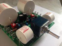
I recently build a Jaycar KC5159 preamp.
Universal Stereo Preamplifier Kit | Jaycar Electronics New Zealand

It comes with different equalisation options: RIAA, Tape, and mic.
I chose tape as that sounded like the closest to a DAC source (Musical Fidelity Xdac V3).
I changed 1 or 2 values to use some nicer parts I had lying around. I changed the 47uf bipolar caps on the input to .47uf polyester caps.
I also changed the 100R resistor on the output to 150R as I had a some nice dale 150R resistors.
I also wired a generic jaycar 50k log pot on the input for volume control.

Everything tested fine, the circuit functioned but as some might guess had some sound issues.
1) The volume was extremely sensitive with the finest adjustment taking volume from quiet to deafening. My current thinking is that this is due to the 100k resistor in parallel with the log pot at the input.
2) Music just sounded weird. My thinking is that this is due to the tape equalisation applied in the feedback network which from the curves I've seen is designed to boost base response and roll off higher frequencies.
This is what I am looking at for version 2.
1) Removal of the equalisation by substituting the feedback network resistors for 10k on both sides
2) Decreased gain as I don't need a huge amount. A gain of 2 should be sufficient I think.
3) Removing the inductor on the input as it doesn't seem necessary from a digital source.
4)Changing the volume control to a 100k linear pot with a 12k parallel resistor as per Rod Elliot's a better volume control ESP - A Better Volume Control
Here is what I have come up with.

Is this likely to have the desired outcome?
I recently build a Jaycar KC5159 preamp.
Universal Stereo Preamplifier Kit | Jaycar Electronics New Zealand
It comes with different equalisation options: RIAA, Tape, and mic.
I chose tape as that sounded like the closest to a DAC source (Musical Fidelity Xdac V3).
I changed 1 or 2 values to use some nicer parts I had lying around. I changed the 47uf bipolar caps on the input to .47uf polyester caps.
I also changed the 100R resistor on the output to 150R as I had a some nice dale 150R resistors.
I also wired a generic jaycar 50k log pot on the input for volume control.
Everything tested fine, the circuit functioned but as some might guess had some sound issues.
1) The volume was extremely sensitive with the finest adjustment taking volume from quiet to deafening. My current thinking is that this is due to the 100k resistor in parallel with the log pot at the input.
2) Music just sounded weird. My thinking is that this is due to the tape equalisation applied in the feedback network which from the curves I've seen is designed to boost base response and roll off higher frequencies.
This is what I am looking at for version 2.
1) Removal of the equalisation by substituting the feedback network resistors for 10k on both sides
2) Decreased gain as I don't need a huge amount. A gain of 2 should be sufficient I think.
3) Removing the inductor on the input as it doesn't seem necessary from a digital source.
4)Changing the volume control to a 100k linear pot with a 12k parallel resistor as per Rod Elliot's a better volume control ESP - A Better Volume Control
Here is what I have come up with.
Is this likely to have the desired outcome?
Much better, just add a 100k to ground after the input coupling capacitor.
like so?

The board has pads for 100nf decoupling caps on each supply rail.
I'm using some Wima mks2 caps I had lying around as I didn't like the look of the no name stuff that came with the kit.
Regarding the coupling caps; I am going to order some wima mks2 1uf 63vdc caps for input and output since I want to replace the LM833N that came with the kit.
like so?
View attachment 781257
The following three potential issues are apparent:
1) You can/should remove the 100k resistor at the input (just after the 1uF input coupling cap) and relocate the 100k volume pot. there. Which, I believe, is what rayma has suggested. Locating the volume pot. after the input coupling cap would ensure that no D.C. appears across the volume pot. That could be an issue because, as it is now, changing the volume would also change the level of any D.C. applied to the input coupling cap. Yes, the input cap. would block that D.C., but there would be a low frequency transient produced each time you change the volume setting, typically resulting in a 'swooshing' sound. No physical harm is probably done to your system, but it could be an audible annoyance, besides making your preamp scream amateur DIY.
2) you can bypass (eliminate) the 47uF bipolar capacitor connecting the feedback network to ground. In other words, terminate the network directly to ground. Yes, the closed loop gain at D.C. will double from unity, however, that shouldn't present a problem as any input D.C. is already blocked by the 1uF input coupling cap. Therefore, the doubling in D.C. gain only affects the op-amp's intrinsic voltage offset. Which is specified at 700uV worst case, which therefore becomes 1.4mV worst case. Either of which is completely blocked by the 1uF output coupling capacitor. Which leads to point three.
3) The 1uF output capacitor is probably too small, unless, as was indicated by rayma, the power amplifier has a very high input impedance. Meaning, roughly 100k or higher. The impedance defining the required value of the output coupling capacitor is the 1M resistor connecting the output cap. to ground in parallel with the input impedance of the next stage. An undersized output cap. will cause bass roll-off. A rough rule-of-thumb I like to use for relating the required size of the output coupling capacitor to the input impedance of the next stage it is coupled to is:
100k > 1uF
50k > 2uF
25k > 4uF
20k > 5uF
10k > 10uF
Last edited:
A line preamp shouldn't be doing any equalization by default. It might have tone controls to adjust for room response or personal preference, but equalization is a gross distortion of frequency response used to undo the opposite gross distortion of frequency response inherent in a vinyl or tape playback cartridge/head.2) Music just sounded weird. My thinking is that this is due to the tape equalisation applied in the feedback network which from the curves I've seen is designed to boost base response and roll off higher frequencies.
This is a preamp for vinyl, tape head, or dynamic microphone only.
I overlooked that you are utilizing the linear pot. based volume control of Elliott Sound Lab. That 12k resistor on the wiper will greatly lower the resistance as seen across the pot., depending on the wiper's setting. This would likely necessitate a larger value for the input coupling cap., so as to not cause bass roll-off. This is how circuits typically present themselves, you usually have to give up something in order to gain something else.
Regarding the output cap value.If I understand correctly:
A) The output coupling cap and the 1M parallel resistor form a high pass filter.
B) Assuming premise (A) is correct. I would also think that this filter also includes the input impedance of the load in parallel with the 1M on the output. In this case that is 25k input impedance for a Marchand Electronics XM9 active crossover.
C)Assuming that (B) is correct that would give an ESR of:
ESR=product over the sum
=(1000000*25000)/(1000000+25000)
=24390.24
giving a corner frequency of:
Fo= 1/(2*Pi*RC)
=1(2*pi*24930.24*0.000001)
=6.53Hz
Assuming that (c) is correct, if I was to leave the existing .33uf cap in there it would give a corner frequency of 19.78hz which seems like an acceptable response (tube power amps).
Is my working correct or have I missed something?
Last edited:
Regarding the output cap value.If I understand correctly:
A) The output coupling cap and the 1M parallel resistor form a high pass filter.
B) Assuming premise (A) is correct. I would also think that this filter also includes the input impedance of the load in parallel with the 1M on the output. In this case that is 25k input impedance for a Marchand Electronics XM9 active crossover.
C)Assuming that (B) is correct that would give an ESR of:
ESR=product over the sum
=(1000000*25000)/(1000000+25000)
=24390.24
giving a corner frequency of:
Fo= 1/(2*Pi*RC)
=1(2*pi*24930.24*0.000001)
=6.53Hz
Assuming that (c) is correct, if I was to leave the existing .33uf cap in there it would give a corner frequency of 19.78hz which seems like an acceptable response (tube power amps).
Is my working correct or have I missed something?
Yes, you have this essentially correct. What's missing is to target a corner frequency which would make the desired listening band flat. A common rule of thumb is to compute a corner frequency which is a decade lower than the lowest frequency you desire to be flat. For example, should you want flat response down to 20Hz, then target and compute for a corner frequency of 2Hz. Should you want flat response to 50Hz, target a corner frequency of 5Hz. Targeting a decade lower corner is simply rule-of-thumb. Rules-of-thumb often contain wisdom, however, that helps speed up our design work, while giving results that are good enough for 99% of the design cases.
A much smaller value output coupling capacitor than computed above may subjectively suffice, especially should your speakers, or your music choice not contain much deep bass. Or, perhaps, deep bass simply isn't a listening priority for you in general. So, use whatever value which sounds sufficient in deep bass to your ears. Just be aware that you may missing deep bass which your system and music might otherwise reproduce.
Last edited:
In addition to what's been said already, 10k/10k for the feedback network seems a bit on the high side to me, I think you could go down to 4k7 or 3k3s without having to worry about upsetting typical impedance balance too much. The parts you are looking at can drive this easily, and it would keep the rather high current noise on the LME49720 from becoming an issue. Hint, if you are going NE5532 pick one with lower common-mode distortion than the cheapest (TI) part.like so?
View attachment 781257
Honestly, a lot of opamps should do at least OK in this circuit. Not that much GBW needed at only 6 dB of gain, and output amplitudes are likely to be 1-2 Vrms at best, so no particular slew rate requirements either. You could toss in a plain '4580 (or even NJM4565) and be quite happy with it.
Last edited:
Well Gents,
Thanks for the help and advice.
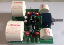
T'was a busy day, but I rewired as per post 5. Except I left the .33uf film cap on the output and reused the same .47uf film caps on the input as I have nothing more appropriate right now.
The sound is downright pleasing. Pretty good for a throw together. Not audio nirvana, but not offensive which is a damn good start.
The bass is rolled off. But you probably knew that was coming.
The volume control works well, nice and smooth control. I was skeptical about the ESP design, but it works much better with a cheap linear pot and the parellel resistor than a cheap log pot.
Its wired with generic Jaycar parts except a few caps I had lying around.
Currently its using the LM833N that came with the kit.
No go fast bits and barely any name brand parts to speak of right now. But this will change shortly as I am due to make an order with element 14.
$10 worth of Opamps, bigger coupling caps and some nicer resistors for the signal path should sort out the LF response and get it going about as good as such a circuit can.
Right now I think its going to have a long and happy service life as the backup preamp for when the main tube premap is on the bench for upgrades.


In case you're wondering. The input coupling caps had to be mounted on the underside of the board due to space constraints.
Thanks for the help and advice.
T'was a busy day, but I rewired as per post 5. Except I left the .33uf film cap on the output and reused the same .47uf film caps on the input as I have nothing more appropriate right now.
The sound is downright pleasing. Pretty good for a throw together. Not audio nirvana, but not offensive which is a damn good start.
The bass is rolled off. But you probably knew that was coming.
The volume control works well, nice and smooth control. I was skeptical about the ESP design, but it works much better with a cheap linear pot and the parellel resistor than a cheap log pot.
Its wired with generic Jaycar parts except a few caps I had lying around.
Currently its using the LM833N that came with the kit.
No go fast bits and barely any name brand parts to speak of right now. But this will change shortly as I am due to make an order with element 14.
$10 worth of Opamps, bigger coupling caps and some nicer resistors for the signal path should sort out the LF response and get it going about as good as such a circuit can.
Right now I think its going to have a long and happy service life as the backup preamp for when the main tube premap is on the bench for upgrades.
In case you're wondering. The input coupling caps had to be mounted on the underside of the board due to space constraints.
Last edited:
Simple OP amp Version 2.0
Hi Guys,
After a couple of weeks usage, I can say that the results are surprisingly pleasing. Of course, the bass is a bit rolled off and it needs upgrades. However, I hate desoldering things, the build used no name parts, the pcb is pretty average and it was only a proof of concept in the first place. I considered just buying a Project 88 board from Rod Elliot @ ESP but I really like the idea of things being dual mono wherever possible.
https://www.diyaudio.com/forums/power-supplies/343228-pcb-fab-attempt.html
I recently discovered how hilariously cheap it is to have pcbs fabbed in China, so, I decided I might just engineer a new one.
www.sound-au.com
I love Rod Elliots work and his website, I think he is one of the heavyweights of the DIY audio world. So in an act gross fanboyism, I plan to ruthless borrow the guts of ESP P88.
My basic idea is to rather than using 1 side of 2 opamps per channel. I would use both sides of 1 opamp per channel. My thinking is that I can then keep everything separate: separate psu rails, separate signal grounds, physically separate boards even.
The idea for the whole project is that most of the time it will sit on a shelf doing nothing. Every now and then one finds a need for a smallish, light and simple preamp (read; no tubes) that can be wacked into a system and simply do decent job. To this end, I think it doesn't need high gain with modern sources. I typically have too much gain rather than not enough. Something around 2 should be sufficient I think.
Here is my working schematic.

By my maths the attached schematic should give me 2.1x gain. This time I plan to use some decent parts so I have designed this for an alps log pot rather than for a linear pot.
Hi Guys,
After a couple of weeks usage, I can say that the results are surprisingly pleasing. Of course, the bass is a bit rolled off and it needs upgrades. However, I hate desoldering things, the build used no name parts, the pcb is pretty average and it was only a proof of concept in the first place. I considered just buying a Project 88 board from Rod Elliot @ ESP but I really like the idea of things being dual mono wherever possible.
https://www.diyaudio.com/forums/power-supplies/343228-pcb-fab-attempt.html
I recently discovered how hilariously cheap it is to have pcbs fabbed in China, so, I decided I might just engineer a new one.
www.sound-au.com
I love Rod Elliots work and his website, I think he is one of the heavyweights of the DIY audio world. So in an act gross fanboyism, I plan to ruthless borrow the guts of ESP P88.
My basic idea is to rather than using 1 side of 2 opamps per channel. I would use both sides of 1 opamp per channel. My thinking is that I can then keep everything separate: separate psu rails, separate signal grounds, physically separate boards even.
The idea for the whole project is that most of the time it will sit on a shelf doing nothing. Every now and then one finds a need for a smallish, light and simple preamp (read; no tubes) that can be wacked into a system and simply do decent job. To this end, I think it doesn't need high gain with modern sources. I typically have too much gain rather than not enough. Something around 2 should be sufficient I think.
Here is my working schematic.
By my maths the attached schematic should give me 2.1x gain. This time I plan to use some decent parts so I have designed this for an alps log pot rather than for a linear pot.
Last edited:


- Status
- This old topic is closed. If you want to reopen this topic, contact a moderator using the "Report Post" button.
- Home
- Source & Line
- Analog Line Level
- Simple opamp preamp issues