I got couple of cassette decks that have audio limiter, some had this feature in the early days. It's actually very useful, not just for recording cassettes but for using as a basic limiter. I use one deck to level TV sound for example. Anyone knows how these actually work? Is it diode based soft clipping or something like that? I don't see anything that would resemble compressor circuit in these decks. It would be great it it was possible to make this limiter as a stand alone.
Last edited:
They are often very simple affairs consisting of a control element such as FET (used as a variable resistance) and a means of driving it in relation to the audio level.
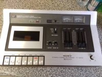
Have a look at some old service manuals to see how it was done. The Sony TC136SD was the first deck I owned and that had a limiter.
Straight from the web:
Have a look at some old service manuals to see how it was done. The Sony TC136SD was the first deck I owned and that had a limiter.
Straight from the web:
Attachments
This IC may be exactly what you are looking for:It would be great it it was possible to make this limiter as a stand alone.
https://www.njr.com/semicon/PDF/NJM2762_E.pdf
I found this diyAudio thread which gives a bit more information on using the IC:
Limiter with njm2762
Limiter with njm2762
They are often very simple affairs consisting of a control element such as FET (used as a variable resistance) and a means of driving it in relation to the audio level.
Have a look at some old service manuals to see how it was done. The Sony TC136SD was the first deck I owned and that had a limiter.
Straight from the web:
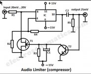
As the collector is biased negative, shouldn't T2 be a PNP? An NPN will act as an emitter follower with very poor hFE because of it being connected in reverse.
Assuming T2 acts as a rectifying common-emitter stage, how can it be turned on by signals of the order of 25 mV when the base-emitter bias voltage is 0?
I agree it does look a bit strange when looked at more closely. Don't believe everything you see on the web ")
The image directs to here. It also mentions a BA741 which I assumed would be a 741 but the pinouts are weird:
https://www.electroschematics.com/322/audio-limiter-circuit-schematic/
Best we look for another example
The image directs to here. It also mentions a BA741 which I assumed would be a 741 but the pinouts are weird:
https://www.electroschematics.com/322/audio-limiter-circuit-schematic/
Best we look for another example
> It would be great it it was possible to make this limiter as a stand alone.
1176 limiter
RNC
dBx-266
Top 20 compressors all time
UA-2a
Gates Sta-Level
Clipping diodes, shearing the peaks away, sound awful.
How would you do it manually?
Keep your hand on the Volume knob. When it gets too-LOUD, turn-down. When it is not-loud and has been turned-down, sneak back to original volume.
People don't do well at this task. Slow, and tend to miss peaks. This was a major problem in talking movies (light-valve clang) and radio broadcasting (overmodulation splatters into adjacent channels, unless the 25,000 Watt modulator blows-up).
What we need is a circuit to reduce gain according to an electrical signal. This signal compares output to a set level, quickly signals "less" when LOUD happens, and slowly signals "more" when the loud has passed.
There are dozens of ways to do this.
The most weekend-friendly plan is well exampled by the Orange Squeezer guitar pedal.
http://beavisaudio.com/schematics/Dan-Armstrong-Orange-Squeezer-Schematic.htm
A resistor and a JFET form a voltage divider. A gain stage boosts-up level, drives output and also a rectifier with separate attack and release time constants. R3 R5 are a cheap trick to reduce JFET (actually circuit) nonlinearity.
The OS is scaled for guitar level. For hi-fi line you may want some attenuation in front. (Yes, leave the gain stage at gain >20 or you will overdrive the JFET.)
Good stereo matching is difficult with JFETs (also LDRs, which are going out of style).
The excellent Nakamichi 550 limiter is the same idea with a fancier rectifier (integrated in the meter driver).
Sony used a BJT.
There are more elaborate methods.
Attachments
Last edited:
I have a TC186SD with limiter. It works with antiparallel diodes. Ilike this machine: simple, robust and reliable.The Sony TC136SD was the first deck I owned and that had a limiter.
Do you remember the old NE570/571 compander chip originally for telecoms applications. That was a great device to play around with. I'm sure there were lots of typical application circuits on the original data sheets.
Wow, it made it to smd form. How is that. I don't feel quite so old now
https://www.onsemi.com/pub/Collateral/SA571-D.PDF
Wow, it made it to smd form. How
is that. I don't feel quite so old now https://www.onsemi.com/pub/Collateral/SA571-D.PDF
I have a TC186SD with limiter. It works with antiparallel diodes. Ilike this machine: simple, robust and reliable.
I remember that one. A work colleague of my fathers had one of those. I also have a mint condition... make that pristine condition TCK5 wrapped up in storage.
I used that one in one of our forum listening tests to make a file and it had everyone guessing because the wow and flutter, although inaudible, meant that the file wouldn't stand up to file analysis and time matching against the digital original. Only when it was revealed that the file was totally analogue did it make sense... and I think everyone thought it sounded pretty good
Post #90
Based on sonics... which do you prefer ?
> shouldn't T2 be a PNP? An NPN will act as an emitter follower with very poor hFE because of it being connected in reverse.
This reverse connection is commonly done with Mute transistors. The limiter is a partial mute.
This is not an Amplifier. We may be able to dump huge current in the Base to control small current in the C-E path.
That said, I sure don't understand the details of what Sony did there.
This reverse connection is commonly done with Mute transistors. The limiter is a partial mute.
This is not an Amplifier. We may be able to dump huge current in the Base to control small current in the C-E path.
That said, I sure don't understand the details of what Sony did there.
> shouldn't T2 be a PNP? An NPN will act as an emitter follower with very poor hFE because of it being connected in reverse.
This reverse connection is commonly done with Mute transistors. The limiter is a partial mute.
I know, but T2 in post #2 doesn't look like a mute transistor to me. It looks more like a rectifier, but then I would expect the emitter to be used as the emitter.
This is not an Amplifier. We may be able to dump huge current in the Base to control small current in the C-E path.
That said, I sure don't understand the details of what Sony did there.
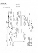
If I understand Mooly's later comment well, the circuit is from an obscure website rather than from Sony.
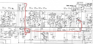
This is the Sony limiter. It takes its input from the headphone amp driver transistor and the control transistor is used to shunt the audio. The line input feed appears to go to the wiper of the input slider pot (top left) via an 82k which is off the page.
Attachments
I was too quick. The machine has a Sony proprietary IC CX-064 that does Dolby B, limiter and all that.I have a TC186SD with limiter. It works with antiparallel diodes. I like this machine: simple, robust and reliable.
Great replies thanks. I think I'll try to build one.
I should just mention that I do have a bunch of compressors in my studio but I wanted one for TV and wasn't going to use something expensive off course for it. I used cassette deck for my TV but it was dying as I was writing my original post. Now it's dead :-(. So I installed sound card in hope to use the sound leveling software but I can't say it works too good. It still peaks to high. So for now I've put in Alesis Micro Limiter. That works perfectly but sometimes I need it in studio.......so anyway, hence me wanting to build the cassette deck limiter which worked real good.
I should just mention that I do have a bunch of compressors in my studio but I wanted one for TV and wasn't going to use something expensive off course for it. I used cassette deck for my TV but it was dying as I was writing my original post. Now it's dead :-(. So I installed sound card in hope to use the sound leveling software but I can't say it works too good. It still peaks to high. So for now I've put in Alesis Micro Limiter. That works perfectly but sometimes I need it in studio.......so anyway, hence me wanting to build the cassette deck limiter which worked real good.
- Status
- This old topic is closed. If you want to reopen this topic, contact a moderator using the "Report Post" button.
- Home
- Source & Line
- Analog Line Level
- Cassette deck audio limiter, how does it work?