The pins are listed as "NC" on the datasheet and TI's standard practice with pins labeled NC means that there is no internal connection to these pins. So, it seems safe to use these pins as a way to route traces through the package. I can't think of a use for these pins either - there are usually no offset adjustment or compensation features on CFB amps, so I'm not sure what else these pins would attach to.
I'm not TI however, and this is not authoritative, but TI does seem to have standards for its documentation, and if a pin has internal connections, they seem to tell you about it and not just say "NC". If you happen to blow one up, you could lift the lid and find out!")
Side cutters can ensure they are NC!!
Hah yes - the 100% correct answer!Side cutters can ensure they are NC!!
Looks like the mods moved my thread to a section that has more eyes on it. I had posted it under Construction Tips.
@Jan
Yes, I had second thoughts on routing the signal output right past the feedback circuit right after I posted it. Groan! I had been in contact with Rayma and he responded that it wasn't optimal. For now, I plan on keeping this project specific to the 49713. With what I learn from this effort, I'll expand to a board with the same form factor so that I can roll op amps and switch boards readily.
@abraxalito
Yes, that vaguely occurred to me on routing R4 north at pin 1 but I didn't follow up on it. Back to the drawing board.
I had an LOL moment about cutting the pin 1 lead. Yeah, no doubt that solves the "is it really a NC or not?" question.
A shout out to rayma for his advice and for pointing out to me about getting the necessary probe for my scope because the 49713 has such a large bandwidth. He's been very generous with his time. I likely won't be able to confirm the full bandwidth, but better than I thought. And my buddy has a network analyzer so I can get an idea on other aspects of performance and report back.
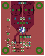
My modus operandus for such relatively simple circuits is to start the layout in the middle of the world box. Lay it out just like the schematic flows. Input left, output right, power supply coming in somewhere from below or above.
Then draw the board edge after all is placed, and move some parts around to make it more compact, with the smallest board possible, with 4 mounting holes in the corners.
A PCB for this normally takes me less than an hour. Make the Gerbers and upload them to Eurocircuits.com to check all manufacturing parameters, label placements, etc. Redo if you see something you don't like.
Then print it out scale 1:1 and check if all parts pins are the right pitch etc. and if all mech parts like heatsinks, pots, headers, connectors etc. fit.
The order them like from seeed.com.
Jan
Last edited:
Thanks for tossing a dog a bone! I'll have a new version posted up.
@Jan Thanks for succinctly showing me how to cover all the bases before placing the order! I get pretty excited like a kid in a candy shop.
@Mark Thanks for the example and I'll learn from this one. I can spin up another board and try this as well.
@Jan Thanks for succinctly showing me how to cover all the bases before placing the order! I get pretty excited like a kid in a candy shop.
@Mark Thanks for the example and I'll learn from this one. I can spin up another board and try this as well.
Quick question - is there a rule of thumb for a value for the electrolytic caps in this application? I just pulled 220 uF out of thin air so not sure if that's too much, too little, or just right. I also have read that a low ESR cap isn't necessarily a good thing so close to the device. True?
I will have the revised layout posted tonight.
I will have the revised layout posted tonight.
Last edited:
Your power traces are making quite a big loop, needlessly so.
I'd suggest rotating the bottom end of C1 to the right by 90° (which would also reduce inductance betwen V+ and V-... C1 and C2 may even end up being able to share a via) and attaching V- in between C1 and C3, and V+ should be able to go in between C2 and C4 with some minimal shifting of C4 and C6.
If you're not worried about symmetry, you could even just reroute V- to C1 while leaving the rest of the layout as-is.
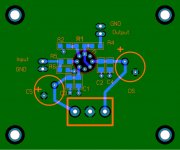
I would move the R2 via to the other side and make an approximately radial slot in the groundplane, going out between R2 and R5 and extending to the outer edge, maybe somewhat below the screw hole. If so, I think I'd want to have the input ground on the top section, closer to the output ground. Hmm, maybe it would be smarter to shuffle the input stuff around and have the slot pass underneath R6 then... turn R6 around, shift C5 down a bit, should be enough room then.
I'd suggest rotating the bottom end of C1 to the right by 90° (which would also reduce inductance betwen V+ and V-... C1 and C2 may even end up being able to share a via) and attaching V- in between C1 and C3, and V+ should be able to go in between C2 and C4 with some minimal shifting of C4 and C6.
If you're not worried about symmetry, you could even just reroute V- to C1 while leaving the rest of the layout as-is.
I would move the R2 via to the other side and make an approximately radial slot in the groundplane, going out between R2 and R5 and extending to the outer edge, maybe somewhat below the screw hole. If so, I think I'd want to have the input ground on the top section, closer to the output ground. Hmm, maybe it would be smarter to shuffle the input stuff around and have the slot pass underneath R6 then... turn R6 around, shift C5 down a bit, should be enough room then.
Could also rotate C1, C3 anticlockwise, straightening out that rail tooLooking good. You could rotate C2, C4 clockwise 90deg and move next to C1. Then move all mounting holes inward for a PCB less than half what it is now ;-)
Jan
Could also rotate C1, C3 anticlockwise, straightening out that rail too
I don't think that brings a lot, though.
Jan
Here's an interesting side story that I have mentioned on the forum before - Corey lived here in Austin and I became friends with a guy who was also still fresh in college like me and made his money selling hi-end equipment at a local store. I believe Corey was a tech at one of the local radio stations at the time.
He was friends with Corey and got Corey to give him some input on developing a high end version that would sell for around $2000 to $3000 a pop. My buddy sold me the parts at cost and I built it up. But knowing what I know now, boy, as pretty as it looks inside (big caps, WIMAs, giant toroid, Penny & Giles pot, silver wire, big telecomm relays), I've learned it has its warts.
He was friends with Corey and got Corey to give him some input on developing a high end version that would sell for around $2000 to $3000 a pop. My buddy sold me the parts at cost and I built it up. But knowing what I know now, boy, as pretty as it looks inside (big caps, WIMAs, giant toroid, Penny & Giles pot, silver wire, big telecomm relays), I've learned it has its warts.
Back again
I had to bow out for a while because a firmware upgrade bricked my router, then my laptop gave up the ghost right after I got the replacement router. And then plumbing emergencies hit. It was a comedy of errors!
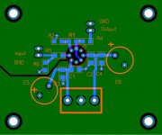
So I took a stab at what you folks have recommended but not sure I got it quite right. If you don't mind, take a look and give me your thoughts. I appreciate the comments.
I had to bow out for a while because a firmware upgrade bricked my router, then my laptop gave up the ghost right after I got the replacement router. And then plumbing emergencies hit. It was a comedy of errors!
So I took a stab at what you folks have recommended but not sure I got it quite right. If you don't mind, take a look and give me your thoughts. I appreciate the comments.
Attachments
- Status
- This old topic is closed. If you want to reopen this topic, contact a moderator using the "Report Post" button.
- Home
- Source & Line
- Analog Line Level
- Need an opinion on layout of LME49713 preamp