Bugs me too. Every time I poke the running man I have to set proper axis parameters. But it's not that big a deal. My initial perception of its graphics capabilities was pretty horrendous and I was actually contemplating going down the complex math route to get my curves or use something like Matlab, Mathematica, etc.
It would be very interesting to find a strong open source version of this tool that included a rich library of components right after installation and that hopefully had a cleaner interface. I'm certain it's out there somewhere.
I'm kind of fond of TI Tina (Here: http://www.ti.com/tool/TINA-TI)...much like LT Spice it's dedicated to TI parts but can create your own spice models if you want. I didn't care for LT Spice because of the steep learning curve, TI Tina is much easier and more intuitive.
Mike
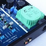
Dear aboos, THANK YOU. You saved me from purchasing an additional board for the AC to DC conversion. It did provide both +-15AC and +-15DC but a simple transformer is more straightforward. I had to power that board with 24V DC, so I would have two transformers in actuality.On the right corner there are diodes for rectification, the smoothing caps and as it looks two regulator chips with the heat sinks. The green connector at the upper right side has three connections so you need 2x15V center tapped AC from a simple mains transformer
Last edited:
So, now I have to get a simple AC transformer.
This unit is based on ESP's design:
Linkwitz-Riley Electronic Crossover
ESP also builds a nice power supply that matches his crossover well:
Power Supply for Preamps
From that page:
"Alternatively, the supply can be run from a conventional split voltage transformer (e.g. 15-0-15V AC). If a split AC supply is used, then the transformer centre tap connects to GND, and the two 15V winding ends connect to AC1 and AC2. Although virtually any transformer of 0.5A or more will work (provided the voltage is correct), there is very little to be gained by using anything more than 30VA (and even that is likely to be overkill)."
I am absolutely convinced that the good people in the far east have integrated part of this power supply on their board, so the text in quotes above applies to their design. I'm trying to figure out the power rating of the transformer to buy.
If I am reading his text right, even a 15VA +-15V AC transformer is enough, supplying the minimum 0.5A current needed. Am I right? Would it make sense to go a bit higher, at 20VA or 25VA?
Lastly, after a little reading about AC transformers (I am a complete electronics newbie), I discovered that toroidal transformers have the property of producing much less EMF interference, and the transformer will sit next to an audio processing circuit. Would you recommend spending the extra cost for a toroidal or will it be something like a 0.5% more noise with a regular transformer?
> power rating of the transformer
It looks like five dual opamps, unknown type. Taking 5mA/opamp, 10mA per chip, that's 50mA DC. Double that for AC Amps, 0.1 Amps AC. 15VAC+15VAC (30VAC CT) seems ample. 30VAC*0.1A AC is 3VA, the minimum transformer.
> less EMF interference
The really teeny 3VA transformers can throw a lot of hum/buzz for their size. I would be looking at 5VA-10VA types. (30VAC CT @ 0.25A)
I do have a doubt. Those regulator heatsinks are WAY bigger than the opamp chips they power. Typically a regulator dissipates 0.6X-1X the heat in the load (opamps). Did they just get a good deal on large heatsinks? Did they spend 2 cents extra to get sinks that look WOW! in the picture? Also the diodes look like 3A jobs when the 1A 1N400x type should be over-ample. I suspect you are right: the designer and the merchant are totally separate parties, good-looking trumps taut engineering, and you won't get technical info from the seller. But hey, it's cheap!! Inspect for bad solder. Wire it up. See if it smokes. With voltmeter black on ground, you expect +/-22V DC on pins of big caps, +/-15V DC on opamp power pins.
Most op-amps only draw a few milliamps at most. As an example, the Texas Instruments NE5532 datasheet shows a typical 8 mA draw per dual op-amp, and a maximum of 16 mA.I'm trying to figure out the power rating of the transformer to buy.
Your board has five op-amps, so 40 mA typical, and 80 mA max draw. Times 30 volts (+/- 15V) that's still only 2.4 watts, worst case. A 5VA transformer will have a nice big safety margin.
Edit: I see PRR beat me to it.
There have been millions of audio circuits built with conventional audio transformers, and negligible noise (i.e. far below audibility)....the transformer will sit next to an audio processing circuit. Would you recommend spending the extra cost for a toroidal or will it be something like a 0.5% more noise with a regular transformer?
That said, this requires good layout and grounding, and distance is your friend - physical distance between the noisy transformer, and the sensitive front-end electronics.
If the transformer is right up against the circuitry, a toroidal transformer will certainly make it easier to achieve good hum and noise performance. If you can find one that doesn't carry a big price penalty, I would say it's worth getting.
I'm a bit concerned about the three transformer-to-board wires, which carry AC with a nasty spiky waveform (because of the way diode rectifiers work), and run right up to the PCB. Wires carrying AC will radiate some noise no matter what type of transformer you use, and wires carrying AC with a spiky waveform will typically radiate more noise and buzz than wires carrying pure sine-wave AC (some of the noise isn't radiated, but coupled to the circuitry through stray capacitance.)
We can only hope that whoever designed the PCB paid attention to detail and made sure this AC-to-board layout still produces acceptable noise.
If I were building this filter from scratch, I would convert the AC to regulated DC on a separate PCB at a safe distance from the sensitive audio circuitry, and then run three wires carrying only DC (which doesn't radiate electromagnetic noise.)
I suggest trying the board as designed. If there proves to be too much hum and buzz, you can always convert the AC to DC off-board, and feed the board with DC. The on-board diodes won't have much work to do, but the board should work just fine.
-Gnobuddy
Last edited:
> power rating of the transformer
It looks like five dual opamps, unknown type. Taking 5mA/opamp, 10mA per chip, that's 50mA DC. Double that for AC Amps, 0.1 Amps AC. 15VAC+15VAC (30VAC CT) seems ample. 30VAC*0.1A AC is 3VA, the minimum transformer.
> less EMF interference
The really teeny 3VA transformers can throw a lot of hum/buzz for their size. I would be looking at 5VA-10VA types. (30VAC CT @ 0.25A)
I do have a doubt. Those regulator heatsinks are WAY bigger than the opamp chips they power. Typically a regulator dissipates 0.6X-1X the heat in the load (opamps). Did they just get a good deal on large heatsinks? Did they spend 2 cents extra to get sinks that look WOW! in the picture? Also the diodes look like 3A jobs when the 1A 1N400x type should be over-ample. I suspect you are right: the designer and the merchant are totally separate parties, good-looking trumps taut engineering, and you won't get technical info from the seller. But hey, it's cheap!! Inspect for bad solder. Wire it up. See if it smokes. With voltmeter black on ground, you expect +/-22V DC on pins of big caps, +/-15V DC on opamp power pins.
THANK YOU for the sagely wisdom dispensed. Opamps are the usual suspect, dual NE5532s. Not sure if this changes anything significantly, but in any case you mentioned noise, so a higher power transformer will cover anything surplus. I'm surprised that required power is an order of magnitude less than what ESP mentions, even if it's an absolute minimum calculation.
The way they "work" is probably having the boards almost ready and just soldering 8 resistors to set the frequency. I expect scary things visually and even a short or two. Really pressing fast work conditions, therefore my quotes earlier. I will most certainly make the measurements you mention, and thanks again. I'm grateful for any tiny bit of wisdom/knowledge dispensed.
If I were building this filter from scratch, I would convert the AC to regulated DC on a separate PCB at a safe distance from the sensitive audio circuitry, and then run three wires carrying only DC (which doesn't radiate electromagnetic noise.)
I suggest trying the board as designed. If there proves to be too much hum and buzz, you can always convert the AC to DC off-board, and feed the board with DC. The on-board diodes won't have much work to do, but the board should work just fine.
Very interesting. This is in fact what ESP does, separate power supply that feeds the LR board with +-15VDC.
Could you clarify on what is acceptable as input on the three pins of the board since by design it wants +-15VAC (and by +- I mean phase of course). What other configurations could make it work the same way? The way you describe it is sounds like I can just substitute +-15VAC with +-15VDC and eliminate AC noise, if it's there.
Last edited:
Without actually seeing the board (or better, the schematic for the board), I'm making an educated guess. (It might help if you provide a link to the board you bought.)The way you describe it is sounds like I can just substitute +-15VAC with +-15VDC and eliminate AC noise, if it's there.
I can't actually see that end of the board in the photo you posted, but it looks as though it has four diodes onboard. Almost certainly they are wired as a full wave bridge. The two ends of your 30V AC transformer winding feed the bridge, and the centre-tap (the "0" in the 15-0-15) provides a voltage halfway between the other two.
As designed, the four diodes rectify the incoming AC, steering positive half-cycles to one supply rail, and negative half-cycles to the other.
Now, if you replace your transformer with a +15V DC, 0V, -15V DC power supply, everything still works normally. Only two of the four diodes in the bridge will be in operation (because the incoming voltage never reverses polarity). Those two diodes won't be doing anything useful, because there is no AC to convert to DC. But they'll still conduct, and allow the incoming DC to flow through them.
So yes, all you have to do is connect +DC to the point on the pad where you normally connect one end of the 30V AC winding. 0V DC goes to the same place the centre-tap of that 30V AC winding would otherwise go. And you connect your -DC where the other end of the 30V AC winding would have gone.
15 V AC RMS (one half of the 30V winding) rectifies to about 21 V DC, less two diode losses of about 0.5 - 0.7 volts each. Each voltage regulator chip on your board is therefore being fed something close to 20 V DC, either + or - as appropriate, which is then regulated down to +15V and -15V.
If you choose to power your board with DC rather than AC, you'll want to provide a similar voltage - roughly +/- 20 volts DC.
You can get this from a modern switching supply or two, or from an old-fashioned 60 Hz transformer, toroidal or otherwise. If you use a transformer, you'll want a 15-0-15 VAC transformer...because after you rectify it to DC (off-board), it will turn into the +/- 20V DC you need.
-Gnobuddy
So yes, all you have to do is connect +DC to the point on the pad where you normally connect one end of the 30V AC winding. 0V DC goes to the same place the centre-tap of that 30V AC winding would otherwise go. And you connect your -DC where the other end of the 30V AC winding would have gone.
15 V AC RMS (one half of the 30V winding) rectifies to about 21 V DC, less two diode losses of about 0.5 - 0.7 volts each. Each voltage regulator chip on your board is therefore being fed something close to 20 V DC, either + or - as appropriate, which is then regulated down to +15V and -15V.
If you choose to power your board with DC rather than AC, you'll want to provide a similar voltage - roughly +/- 20 volts DC.
You can get this from a modern switching supply or two, or from an old-fashioned 60 Hz transformer, toroidal or otherwise. If you use a transformer, you'll want a 15-0-15 VAC transformer...because after you rectify it to DC (off-board), it will turn into the +/- 20V DC you need.
Given things on the board are as you suspect, it's just as I imagined. Substitute AC with DC, just with a different amplitude.
I found a completed LR product there in the far east, and zoomed into it's toroidal transformer:
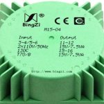
And further research shows it's this, it's a PCB mounted version:
So the people in the far east are using a 15VA transformer. Perhaps they are aware of noise problems at lower power ratings. Perhaps it costs the same to make a 10VA transformer. I trust you guys however, in that this board's demands are nowhere near 15VA.
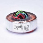
This green thing costs something like 20$. I almost got it until I found a different toroidal, 30VA mind you, for something like 13$ so I just snatched it. If it works, cheap is good in this case:
It has a dual primary winding so I imagine I have to very carefully connect them in series so that it properly works in my country (Greece, 230V-240V) and nothing blows up.
So I am super excitedly waiting for these two components to play with.

A final note: After your earlier calculations about the board's current draw, I had my reservations because of the text from ESP's power supply description: "If a split AC supply is used (such as 15-0-15V AC), then the transformer centre tap connects to GND, and the two 15V winding ends connect to AC1 and AC2. Although virtually any transformer of 0.5A or more will work (provided the voltage is correct), there is very little to be gained by using anything more than 30VA (and even that is likely to be overkill)."
I think my mistake is that this is a description for a generic power supply for preamplifiers. Other boards may have much higher demands, hence the high-ish 30VA rating he recommends (ten times what I need in this case). Regardless, I ended up getting a 30VA after all, just because of the price.
As a second side note, and because LR is pretty much finished in this thread for now, I am installing eSim and KiCad and attempting to recreate/simulate the same circuit I made in LTspice. See if and how things work out.
")
Attachments
One of the nice things about science and engineering is that you rarely have to trust someone's opinion: the answers are there in science and math, calculable and verifiable facts. As we all know, opinions can sometimes be dangerously wrong, so it's really nice to have facts to depend on.I trust you guys however, in that this board's demands are nowhere near 15VA.
We already had a look at the TI datasheet, and worked out power consumption of the board based on the 5532 op-amps current draw. Now lets try a different tack, this time based on thermodynamics. How much power can a little IC of that size dissipate before it heats up so much that silicon devices fail?
This table ( Package Thermal Resistance Values (Theta JA, Theta JC) for Temperature Sensors and 1-Wire Devices - Application Note - Maxim ) says that an 8-pin DIP package (the one your op-amps come in) will heat up by 110 degrees Celsius if you dissipate one watt, with the chip mounted to a two-layer copper PCB. If your PCB is in a room at, say, 20 C, that means the chips heat up to 130 C.
Silicon devices will usually fail at 150 degrees C, but that is an abusively high temperature; nobody who cares about reliability will operate them anywhere near that temperature, or anywhere near 130 C, for that matter.
But, just to make the point, let's take the ridiculous over-estimate; all five of your op-amps are boiling hot, dissipating one watt each. That makes five watts total power draw. Add another two watts for the overheated voltage regulators, you're up to 7 W total power demand.
So, just from thermal considerations, if all seven chips on your board were hot enough to cook an egg on, your board would still only need maybe 7 watts from the transformer!
Your fingertip is all you need to verify that the 5 op-amps are not, in fact, anywhere near that hot...ergo, they are in fact dissipating much less than 1 watt each. (At the specified 8 mA draw per chip, actual dissipation would be around 240 mW with +/- 15V supply rails, i.e. around one quarter of a watt.)
I read this as saying "15 VA is plenty, but if you like ludicrous excess, by all means go up to 30 VA, even though you will gain nothing by doing so.""...any transformer of 0.5A or more...little to be gained by using anything more than 30VA (and even that is likely to be overkill)."
Good engineers are always conservative - nobody wants to be associated with a circuit that blows up regularly. I'm sure Mr. Linkwitz knows his circuit draws barely 1.2 watts. But a 15VA power supply isn't much more expensive, and offers a huge safety margin, so why not use it?
I look forward to your results. I've used KiCad a few times to draw schematics, but I've never tried using it to simulate anything....eSim and KiCad...
KiCad's library management process has beaten me to a standstill. I attempted to create a part of my own (an oddball vacuum tube), and create a library containing it. I found about five tutorials online on how to do this, each one contradicting the other. KiCad itself didn't correspond to any of the tutorial instructions, just to round out the frustration.
-Gnobuddy
I read this as saying "15 VA is plenty, but if you like ludicrous excess, by all means go up to 30 VA, even though you will gain nothing by doing so."
Good engineers are always conservative - nobody wants to be associated with a circuit that blows up regularly. I'm sure Mr. Linkwitz knows his circuit draws barely 1.2 watts. But a 15VA power supply isn't much more expensive, and offers a huge safety margin, so why not use it?
I look forward to your results. I've used KiCad a few times to draw schematics, but I've never tried using it to simulate anything.
KiCad's library management process has beaten me to a standstill. I attempted to create a part of my own (an oddball vacuum tube), and create a library containing it. I found about five tutorials online on how to do this, each one contradicting the other. KiCad itself didn't correspond to any of the tutorial instructions, just to round out the frustration.
-Gnobuddy
Nice analysis from a thermal standpoint.

You just interrupted (and probably stopped) my effort at making that LR schematic in KiCad. It's good cause I need some sleep. About eSim, I did not manage to run it, and personally would not recommend an installation of it on a Windows system, due to dependencies. It's a bundle of all sorts of things much like KiCad, only KiCad seems better integrated. Perhaps a Linux distribution can manage eSim's dependencies better.
Just to clarify who said what (cause I think it's very important) the 30VA was not Siegfried Linkwitz's recommendation, but Rod Elliot's. He's from Australia and designs/builds neat stuff. By the way, I was glad to see Linkwitz is still around, unlike Butterworth for example. Even has his own website online (linkwitzlab) where he explains his own creations.
But returning to the recommendation, that was not intended for the LR board itself, but a separate power supply board ESP makes which can power their LR board with +-15VDC. He calls it "preamplifier power supply", so I am guessing the 30VA recommendation for it is for covering various types of preamplifier boards that involve gain (unlike the LR crossover) therefore more power draw.
Last edited:
Oh, don't let me stop you! The schematic-drawing side of KiCad seemed quite nice, as long as you're using parts provided in the built-in libraries. I only encountered major headaches trying to make my own part....probably stopped...my effort at making that LR schematic in KiCad.
The only thing I recommend installing on a Windows system is Linux, making sure you completely erase Windows in the process.would not recommend an installation of it on a Windows system
I'm familiar with his website. Lots of neat designs there....Rod Elliot's.
Gotcha.He calls it "preamplifier power supply", so I am guessing the 30VA recommendation for it is for covering various types of preamplifier boards
Times have changed, and next time I need an op-amp power supply, I plan to use one of these: RAC10-12DK/277 Recom Power | Power Supplies - Board Mount | DigiKey
It's a tiny little brick that you feed 120V (or 240V) into at one end (two pins), and DC voltage comes out the other: three pins carrying +12V, 0V, and -12V respectively. Most op-amps will run very happily on +/- 12V instead of +/- 15V.
There is a +/- 15V DC version of the same module, but for some reason, it costs twice as much. There's lower demand for it, I expect.
I will add an external stage of RC filtering to reduce ripple. The switching frequency is high, so it doesn't take a lot of RC filtering to dramatically reduce the remaining ripple.
-Gnobuddy
> labelling my output would automagically include that label
I'm not an LTSpice user, but am again poking at it.
The "label" is human-arbitrary, SPICE (generally) would not presume to understand humans.
I *now* see that LTSpice's labels have an option for None, In, Out, or Bi-Di. Apparently this only affects the *drawing*, whether the arrow points in or out. Other than drawing rendering, it seems to have no effect. Used well, it may help humans see/think more clearly. OTOH, the tutorial I was following said to call a label "in" and make it Type "output". That was meant to connect a source to a load over an un-drawn "line" called "in".
Yeah, I didn't get how to plot until I hovered the cursor around and saw it changed to a "funny pencil" (meter/scope probe). I like my old sim which had a probe "part" I could leave on the drawing run to run.
I now know that both old-PSpice and new LTSpice give me a kink in the back. Even more than text-editing, circuit-editing strains me.
And what is with LTSpice's F9 for undo??? WTF uses F9 for undo? (I undo a lot.) Tip: most keystrokes can be re-assigned in a menu. Ctrl-Z (undo in 99% of apps) happens to conflict with some Zoom command so I nuked the conflicter (I think to Ctrl-A).
Last edited:
I've noticed that if I do the Plot Settings -> Save Plot Settings thing, after that LTSpice will redraw my graphs every time I click on the running man icon, without my having to probe the output(s). I'm not sure if this happens every single time I do the "Save Plot Settings" thing, but it certainly happens often....I like my old sim which had a probe "part" I could leave on the drawing run to run.
I feel the same. And for some reason, schematics drawn with LTSpice cause much more eye / mental strain than, say, schematics drawn with KiCad. Something to do with the jagged lines and sharp corners and crudely drawn symbols, I suspect.Even more than text-editing, circuit-editing strains me.
-Gnobuddy
You're quite welcome!Thanks for the tip! (Can't find all this stuff in one day...)
I've spent a lot more than a day tinkering with LTSpice, and there are still a tonne of things I don't know about its capabilities.
-Gnobuddy
I've worked in PSpice (and priors) for 30+ years and still find little tricks.
I noted something in LTSpice which can be useful. After a DC (.op) run, if you hover parts on the schematic, the power dissipation appears in the bottom of the window. (At least resistors and batteries; don't have a tube/transistor on the bench yet.)
This would almost be useful for a question which came up elsewhere: what resistors to use for a HIGH power switched attenuator. He had plan and values but not power ratings. The problem can be solved with DC: put 28.28VDC in, that's same-as 100W @ 8r. But the resistors are in two switched strings, 8 steps, any one of the resistors "could" be the hot one (inspection will suggest the worst case but I guessed wrong a few tries), so 8*18=144 values to compute. A spreadsheet would do it in an instant but setting-up would a tedious chore. (I advised building with all 10W, spread out, feed 24VDC, nose/finger check for hot or cold parts, watching that output voltage is nominal (nothing blew yet).)
Do you use pot? Does your pot blow-up if setting is zero or 1? (Divide by zero error.) There is an elegant fix. Maybe everybody knows but me.
I've used that trick too. A very useful tip.After a DC (.op) run, if you hover parts on the schematic, the power dissipation appears in the bottom of the window.
There is also a way to manually enter an equation to plot, and that equation can, for instance, be (some current) * (voltage1 - voltage2), so you can plot power dissipation in a device against time if you want, even if that device has no grounded terminals.
A while ago I was trying to design a variable guitar amp speaker attenuator, but the input impedance needed to be reasonably constant at around 8 ohms. The question was how to calculate that input impedance across the audio frequency range (the attenuator included reactive elements as well as resistors.)
In LTSpice, I found I could insert a 1 milli-ohm resistor in series with the input to the attenuator. That makes the current into the input port easily accessible within LTSpice. With that available, I could then plot (input voltage / input current). Voila, input impedance as a function of frequency!
More on how to enter your own equations to plot in this tutorial: https://www.digikey.com/eewiki/display/Motley/LTspice+Tips+-+Plot+Manually+Entered+Functions
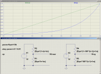
The pot model wasn't included when I downloaded LTSpice (apparently it was included in some older versions), so I rolled my own, see attached image.Do you use pot? Does your pot blow-up if setting is zero or 1?
(Divide by zero error.) There is an elegant fix.
The good: I was able to figure out the equations to make a standard audio-taper log pot, as well as a linear pot. They're in the attached image.
The bad: doing it this way doesn't look like a pot on the schematic, just two ordinary resistors. Understandably, this confuses people.
The ugly: I was able to prevent the equations blowing up at zero pot rotation by adding 1 milli-ohm to each equation. It works, and the error is negligible when the pot resistance is much greater than 1 milli ohm. But this kludge is far from elegant.
The ridiculous: I attempted to follow a couple of tutorials on how to create your own pot model (which means it looks like a pot, and uses the equations you type in.) I failed two or three times, then decided it wasn't worth spending more time on.
I also downloaded the old LTSpice pot model from somewhere and tried to incorporate that into my version of LTSpice. The results were erratic and unreliable, so after more wasted time, I gave up on that as well.
These days I feel that what's left of my life is too short to waste hours struggling with uncoperative software. So if I find a workaround, I take it, and move on.
-Gnobuddy
Attachments
- Status
- This old topic is closed. If you want to reopen this topic, contact a moderator using the "Report Post" button.
- Home
- Source & Line
- Analog Line Level
- Help needed: Linkwitz-Riley frequency response curves