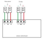
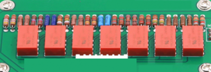
I'm just running trials on a remote volume control 12VAC board (really a stepped attenuator using relays and resistors) placed externally between source and amp through RCA sockets (please look at the pic in attachment).
Connections are extremely simple, just as the drawing in attachment and the original volume potentiometer (if existing) has to be be bypassed or set to 10 (max) and then you can adjust the volume level using the remote control unit.
Sure it does work, but also it adds more 4 couples of RCA sockets and a cable on signal path.
So I just wonder if there was a way in order to place the board inside my integrated amplifier exploiting wires that connect to IN and OUT (and GND) pins of the original ALPS stereo potentiometer in order to "remove" those 4 couples of RCA sockets (and that further cable) on the signal path.
Any addressing will be more than welcome.
Many thanks in advance!
Attachments
I'm just running trials on a remote volume control 12VAC board (really a stepped attenuator using relays and resistors) placed externally between source and amp through RCA sockets (please look at the pic in attachment).
Connections are extremely simple, just as the drawing in attachment and the original volume potentiometer (if existing) has to be be bypassed or set to 10 (max) and then you can adjust the volume level using the remote control unit.
Sure it does work, but also it adds more 4 couples of RCA sockets and a cable on signal path.
So I just wonder if there was a way in order to place the board inside my integrated amplifier exploiting wires that connect to IN and OUT (and GND) pins of the original ALPS stereo potentiometer in order to "remove" those 4 couples of RCA sockets (and that further cable) on the signal path.
Any addressing will be more than welcome.
Many thanks in advance!
The diagram sadly lacks detail as to what attenuation is being achieved.
Try to draw a schematic of the relay board.
Most common is a series path and a shunt path for each channel for the components on the relay board. If it complies with having a series and shunt for each channel you have what is called a L pad. Each series and shunt paths should have a range of resistances being selected by the relay contacts. It is therefore a form of stepped attenuator
It is unusual to be using both a relay selected stepped attenuator and a pot, at the same time.Rather once you draw a schematic of the relay board - post it here for us to check and you will begin to see its actual purpose. The relay stepped attenuator should provide
a number of resistances ,comfortable enough to adjust your volume levels. If it does not do this, or presents itself as being plainly awkward, ie your description above alludes to having to set a pot at max to then use a remote volume control.
To remove contacts of the volume control which can with better designs also include removal of contacts involved with input switching , you need to use opto coupled methods, These are available with remote volume control ,as kits or built units.
Thanks for your appreciated reply, Chris Daly!
Please note I am not an expert, I imagined that the situation was not so simple though.
Just as matter of the fact I am not able neither to draw out a scheme of functioning of relays and resistors nor to reply in any way to your other appreciated considerations.
The only thing I can say nw is that I tried disconnecting the wires from the potentiometer and connecting them to the board (the wires that were connected to IN on the potentiometer I then connected them to IN on the board and those that were connected to OUT on the potentiometer I disconnected them and connected them to OUT on the board... and then GNDs too), but it doesn't work (that's: nothing come out from loudspeakers).
Thank you!
Please note I am not an expert, I imagined that the situation was not so simple though.
Just as matter of the fact I am not able neither to draw out a scheme of functioning of relays and resistors nor to reply in any way to your other appreciated considerations.
The only thing I can say nw is that I tried disconnecting the wires from the potentiometer and connecting them to the board (the wires that were connected to IN on the potentiometer I then connected them to IN on the board and those that were connected to OUT on the potentiometer I disconnected them and connected them to OUT on the board... and then GNDs too), but it doesn't work (that's: nothing come out from loudspeakers).
Yep, it does exactly that.The relay stepped attenuator should provide
a number of resistances ,comfortable enough to adjust your volume levels.
Thank you!
Yes, you're right.It is unusual to be using both a relay selected stepped attenuator and a pot, at the same time.
Anyway please note that the board is a passive input selector too, then it is a so called passive preamp with a volume control.
So there is no way to use it connected to an existing preamp if not just as it was a device and then to connect its OUT pins to IN sockets on my preamp (really an integrated amplifier with a passive preamp or input selector) and its IN pins to the OUT source sockets.
And the volume pot has to be bypassed or set to "max".
This way as many as 8 RCA sockets (4 male and 4 female) and a more cable will stay on the signal path, and I do not like that.
...place the board inside my integrated amplifier ...
I think we need to know what that amp is to give specific advice.
It is probably "possible" but depends a lot on the details.
That's it was wrong because trying and searching again I finally learned that the OUT pins on the pot are connected to the source.(the wires that were connected to IN on the potentiometer I then connected them to IN on the board and those that were connected to OUT on the potentiometer I disconnected them and connected them to OUT on the board... and then GNDs too), but it doesn't work
It is completely counterintuitive, but that is.
So I revised my soldering points and now my board works fine!
Thanks
- Status
- This old topic is closed. If you want to reopen this topic, contact a moderator using the "Report Post" button.