I've seen where the pot impedance can be lowered by adding a resistor from the wiper to ground (e.g. 6K2 for 50K pot) but I've also read it's not a good idea for a log pot as it alters the audio taper (too much??). Seems to be fine for linear pots such as ESP Project 1 (fake log).
What happens to the behaviour of the pot when this is done or have I answered my own question.
The reason I ask is I have some TPA3116 amps with 50K pots (linear AFAIK) which are hissy and have read where 4K7 was added between the wiper and ground made it quieter. All the TPA3116 amps I have that do not come with a pot are not hissy. I also have a Alps A100K which I'd like to lower the impedance as most of the circuits I've been doing use a A10K pot.
I have some TPA3116 amps with 50K pots (linear AFAIK) which are hissy
and have read where 4K7 was added between the wiper and ground made it quieter.
I also have a Alps A100K which I'd like to lower the impedance as most of the
circuits I've been doing use a A10K pot.
This is fine for a linear pot, but not for a log type.
Last edited:
Assuming that the added resistor does not too greatly load the stage feeding the pot.(meaning, provoke an significant increase in distortion, or reduction in signal level), then, in my view, the net taper created is not that important. The whole idea have having a pot. with a log taper is so that the rotation arc of the pot. seems more proportional to the resulting loudness perceived by the ear. This is, maybe, useful if one desires to accurately set the percieved loudness only by visually setting the volume control rotation. In addition, this suggests that there is some rigidly standard recorded average level which all program content musty adhere to.
I, like, no doubt, most eveyone else, set volume by an aural feedback process of listening and then adjusting the volume until the loudness seems right for that particular program content, and for my listening mood. So, really then, how important is having an accurate log taper - especially with the convienece remote volume control. I suggest you implement the shunt resistor and love with it for awhile to see if it presents any problems in actual use.
I, like, no doubt, most eveyone else, set volume by an aural feedback process of listening and then adjusting the volume until the loudness seems right for that particular program content, and for my listening mood. So, really then, how important is having an accurate log taper - especially with the convienece remote volume control. I suggest you implement the shunt resistor and love with it for awhile to see if it presents any problems in actual use.
Last edited:
An unloaded (or lightly loaded) linear pot is horrible to use. How horrible depends on the system gain. Where a system has even slightly more gain than necessary, all the action seems to happen in the first quarter turn.
Fortunately the pot is sometimes loaded by the following stage, this can improve things a bit.
Fortunately the pot is sometimes loaded by the following stage, this can improve things a bit.
Wow… where to start?
Audio taper pots attempt … with a degree of refinement that depends closely on the attention-to-detail given in production by the manufacturer … deliver over their sweep range a broader controllable range of acoustic levels. By comparison,
Linear taper potentiometers attempt … again with a degree of refinement depending on the attention-to-detail by the manufacturer, to deliver a mathematically linear range of resistance from minimum=0 to maximum=pot value. Dial ½ the way, and ½ the resistance is from left-to-sweep, and from sweep-to-right. This is VERY useful for adjusting voltages (think "bias points"), but not usually very useful for adjusting volume levels over a broad range.
Audiophiles and tinkerers very often replace conventional audio-taper potentiometers — especially “stereo” dual channel ganged units — with 2 pole, many-position rotary switches … and a string of resistors of well-matched (per channel) value, to optimize the exact amplification afforded by one's amplifier stack. But what to choose for the resistor values?
This last question goes to the “heart” of the engineering that is encoded (pardon the pun) in the making of conventional log-taper audio potentiometers. The designer of rotary-switch-or-potentiometer needs to address “what might be most useful”, somehow.
Convention calls for a 50 or 60 dB control-range for either an audio-taper pot or a rotary-encoded switch doing the same function.
In the case of a rotary switch, having say 'N' rotary indents, in a way similar to audio-pot tapers, does not have a directly linear-in-the-aural-intensity-scale formulation; indeed, it is felt that at low acoustic levels, greater 'distance' between 'indents' is more useful than at the higher/highest output end of the scale. For example, when I built my friend's 24 indent rotary volume encoder (stereo), I arbitrarily followed this principle and set:
(my apologies, not terribly readable… but accurate… from PERL output)
So, choosing 2% precision resistors, in the values indicated, I crafted an about–100 kΩ (99.7 kΩ to be exact) 'stack' that delivered the decibels of attenuation indicated on the left column, to ⅛ of a dB of accuracy. Some REALLY “refined golden ears” claim to be able to hear ⅓ or ¼ of a dB difference. I cannot do better than 1 dB except when listening to the purest SINE waves at modest aural intensities. So, ⅛ dB outstanding.
But the point isn't to preen at my selection, but rather to demonstrate the embodiment of the design decision to use an indent-to-indent scale that is close “at the top” (loudest), and rather further apart “at the bottom”. In practice, this design decision (underlined to reinforce the idea that it was a purposeful-decision, but still essentially arbitrary!) drove the rest of the math, the math drove selection of resistor values, the E–48 2% resistance scale determined which particular resistor would be needed, and working with those, back-calculating the dB error “closed the design loop”, satisfying both me (the math-and-engineering goat), and my customer (who wanted a great 100 kΩ pot replacement).
The manufacturer of an audio-taper pot attempts to achieve something similar, giving a broad enough dB attenuation range to be “useful” to the person employing it for volume-setting and volume-adjustment purposes. Whether in fact they do so with sufficient accuracy to not offend our dear Golden Ears, well … that is a matter of substantial controversy and heated discussion.
Feel free to use the above resistance values if you are building a 100 k, 24 section stereo switched pot replacement. They work out well.
Just saying,
GoatGuy ✓
Audio taper pots attempt … with a degree of refinement that depends closely on the attention-to-detail given in production by the manufacturer … deliver over their sweep range a broader controllable range of acoustic levels. By comparison,
Linear taper potentiometers attempt … again with a degree of refinement depending on the attention-to-detail by the manufacturer, to deliver a mathematically linear range of resistance from minimum=0 to maximum=pot value. Dial ½ the way, and ½ the resistance is from left-to-sweep, and from sweep-to-right. This is VERY useful for adjusting voltages (think "bias points"), but not usually very useful for adjusting volume levels over a broad range.
Audiophiles and tinkerers very often replace conventional audio-taper potentiometers — especially “stereo” dual channel ganged units — with 2 pole, many-position rotary switches … and a string of resistors of well-matched (per channel) value, to optimize the exact amplification afforded by one's amplifier stack. But what to choose for the resistor values?
This last question goes to the “heart” of the engineering that is encoded (pardon the pun) in the making of conventional log-taper audio potentiometers. The designer of rotary-switch-or-potentiometer needs to address “what might be most useful”, somehow.
Convention calls for a 50 or 60 dB control-range for either an audio-taper pot or a rotary-encoded switch doing the same function.
In the case of a rotary switch, having say 'N' rotary indents, in a way similar to audio-pot tapers, does not have a directly linear-in-the-aural-intensity-scale formulation; indeed, it is felt that at low acoustic levels, greater 'distance' between 'indents' is more useful than at the higher/highest output end of the scale. For example, when I built my friend's 24 indent rotary volume encoder (stereo), I arbitrarily followed this principle and set:
(my apologies, not terribly readable… but accurate… from PERL output)
Code:
               99,658.6 = ohms
dB             48          dB
20log ratio    E-scale     ERROR
  0
 –2            20,500.0    0.00
 –4            16,200.0    0.01
 –6            12,700.0    0.05
 –8            10,500.0    0.02
–10             8,250.0    0.00
–12             6,490.0    0.01
–14             5,110.0    0.01
–16             4,020.0    0.05
–18             3,320.0    0.02
–20             2,610.0    0.01
–23             2,870.0    0.04
–26             2,050.0    0.08
–29             1,470.0    0.08
–32             1,050.0    0.05
–35               750.0    0.02
–38               511.0    0.02
–42               464.0    0.02
–46               287.0    0.12
–50               187.0    0.12
–55               140.0    0.12
–60                78.7    0.11
–66                51.1    0.03
–72                24.9    0.05
–200               24.9    0.00
So, choosing 2% precision resistors, in the values indicated, I crafted an about–100 kΩ (99.7 kΩ to be exact) 'stack' that delivered the decibels of attenuation indicated on the left column, to ⅛ of a dB of accuracy. Some REALLY “refined golden ears” claim to be able to hear ⅓ or ¼ of a dB difference. I cannot do better than 1 dB except when listening to the purest SINE waves at modest aural intensities. So, ⅛ dB outstanding.
But the point isn't to preen at my selection, but rather to demonstrate the embodiment of the design decision to use an indent-to-indent scale that is close “at the top” (loudest), and rather further apart “at the bottom”. In practice, this design decision (underlined to reinforce the idea that it was a purposeful-decision, but still essentially arbitrary!) drove the rest of the math, the math drove selection of resistor values, the E–48 2% resistance scale determined which particular resistor would be needed, and working with those, back-calculating the dB error “closed the design loop”, satisfying both me (the math-and-engineering goat), and my customer (who wanted a great 100 kΩ pot replacement).
The manufacturer of an audio-taper pot attempts to achieve something similar, giving a broad enough dB attenuation range to be “useful” to the person employing it for volume-setting and volume-adjustment purposes. Whether in fact they do so with sufficient accuracy to not offend our dear Golden Ears, well … that is a matter of substantial controversy and heated discussion.
Feel free to use the above resistance values if you are building a 100 k, 24 section stereo switched pot replacement. They work out well.
Just saying,
GoatGuy ✓
Last edited:
Resistor-in-parallel-to-pot-wiper...
GABX answered… but not the original poster's point: to add a smallish value (5% to 15% of full pot value) in parallel to the wiper-and-ground (W+G). Being a math-curious sort, I thought it useful to 'play' with this with a smallish c-code program (hey, it could be any language, including Excel if one likes!!!)
Here in a nutshell is what I found.
Without any math at all, the effect of a fixed resistor in parallel with W+G is to make a variable load for the previous stage's output. At 'zero knock' (max counterclockwise), the impedance of the pot's high-to-low terminals is “as specified”. At MAX knock, full clockwise, it becomes
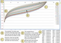
But what about the effect on attenuation-as-a-function-of-rotary-encoding-angle? On a linear encoded pot… Basically, it depends heavily on the value of the parallel resistor. The effect is to both lower the pot (as voltage divider) output across the sweep, except for both ends. Zero and full knock remain same. (-∞ to –0 dB). The one take-away is that the point of maximum unloaded attenuation enhancement is at 50% of full-knock angle. In the case of a 300° pot, that'd be at 150°, or conventionally with the knob pointed straight up.
For example:
The other take-away is that the 'approximation to semilog audio-taper behavior' is made worse with small value parallel resistors, and made 'useless' with large ones. The closest “useful” resistance turned out to be 10% or so. 7% to 15%, to be fair.
Again… remember tho' that the input-facing-load of this technique becomes variable per angle of pot and the value of the resistance chosen, with at maximum impact, the full-clockwise, no-attenuation case being largest.
Now, back to our regular programming. Pun intended.
Just saying,
GoatGuy ✓
Why would you want to lower the input resistance? At best it does no harm; at worst it raises distortion and reduces LF response.
GABX answered… but not the original poster's point: to add a smallish value (5% to 15% of full pot value) in parallel to the wiper-and-ground (W+G). Being a math-curious sort, I thought it useful to 'play' with this with a smallish c-code program (hey, it could be any language, including Excel if one likes!!!)
Here in a nutshell is what I found.
Without any math at all, the effect of a fixed resistor in parallel with W+G is to make a variable load for the previous stage's output. At 'zero knock' (max counterclockwise), the impedance of the pot's high-to-low terminals is “as specified”. At MAX knock, full clockwise, it becomes
REFF = { RPOT || RFIXED }
Obvious. Desired? Ah, now that is a different question! But what about the effect on attenuation-as-a-function-of-rotary-encoding-angle? On a linear encoded pot… Basically, it depends heavily on the value of the parallel resistor. The effect is to both lower the pot (as voltage divider) output across the sweep, except for both ends. Zero and full knock remain same. (-∞ to –0 dB). The one take-away is that the point of maximum unloaded attenuation enhancement is at 50% of full-knock angle. In the case of a 300° pot, that'd be at 150°, or conventionally with the knob pointed straight up.
For example:
Code:
Of R    Angle  dB       ... notes ...
-------------------------------------------------------------
3.0%   150°   –19.4  (–25.4 dB atten vs. –6.0 dB w/o)
5.0%   150°   –15.5  (–21.6 dB atten vs. –6.0 dB w/o)
7.5%   150°   –12.7  (etc.)
10%    150°   –10.9
15%    150°   –8.5
20%    150°   –7.0
30%    150°   –5.3
40%    150°   –4.2
50%    150°   –3.5
60%    150°   –3.0
80%    150°   –2.4
100%   150°   –1.9
150%   150°   –1.3
250%   150°   –0.8
500% 150° –0.4Again… remember tho' that the input-facing-load of this technique becomes variable per angle of pot and the value of the resistance chosen, with at maximum impact, the full-clockwise, no-attenuation case being largest.
Now, back to our regular programming. Pun intended.
Just saying,
GoatGuy ✓
Last edited:
Only if driven from a high impedance source, which would be unusual.gabdx said:it makes less noise,
Adding a law-changing resistor to the pot output has a small downside: it pulls more signal current through the wiper-track interface which is the weakest part of a pot design. Hence any problems developing here may be more noticeable.
- Status
- This old topic is closed. If you want to reopen this topic, contact a moderator using the "Report Post" button.
- Home
- Source & Line
- Analog Line Level
- Lowering the pot impedance