A humble update.
Due to some of the last events, it appears on the surface that the project isn't doing so well, but that is not the case.
I have looked at a few things in the background, but every tiny change / improvement does not require an update.
To give you an idea:
- The optical sensor which register rotation from the code wheel is fully serviceable/available from inside the cabinet as its own module and should make installation and removal fairly simple.
- This allow the code wheel (etched brass) to be installed on the back of the volume wheel. This assembly is the pressed onto the outside ring of the bearing - The inner ring is pressed onto a protruding portion of the front plate, completing this portion of the amplifier.
- This allows for a fully "free floating" display hub to be inserted and mounted inside the wheel and further attached to the front plate on the inside.
- The glass front of the display hub will be sourced from readily available camera lens protection, the screw on type, and is no longer a custom part. Such as UV filter.
- As before, the communication between the display, rotary encoder, buttons and MUSES chips will go through an Arduino - yet another open source part with codes readily available. Even if I don't know a single string of code, I believe this should not be the most challenging thing to get right.
Regarding the PSU:
- I am still divided whetter the transformers and ac/dc section can/should be placed inside the same chassis or use a separate one.
- The main transformers will be Hammond 229 Series and will be both shielded and potted. This should prevent stray EM/RF fields, also make them very quiet.
- The AC side will be separated in a compartment close to the front and blocked off by a thick aluminum wall to separate it from the electronics in the rear.
- This should be considered a premium solution ??? - There are many pre- and power amps that does not go down this rout and all of the PSU section is fully exposed to the main electronics, the interference vary greatly. Using extended shielding should eliminate most of the problems.
- This could be the default solution with a separate PSU as an option for does who which to use that instead. That would require the builder to make his/her own choices and layout in the PSU chassis.
- AC/DC conversion is as mentioned earlier and has not changed.
- Still considering the options for the Arduino power.
The Main Electronics.
- Some of the rules has been laid out, I would prefer if the signal and gnd is on the same plane which demands for surface mounted parts. This should further reduce any signal noise that might exist.
- Designing the motherboard as one card which has all the circuits embedded on it should make things a better and hopefully cheaper since there is only one card to be manufactured.
- For the electrolytic caps, ELNA Silmic-II will be used.
- The Feedback resistor will be placed on the motherboard, underneath the UGS gain stage.
- The main DCV regulator will be placed at the back of the card, closest to the transformers and at a distance to the main control circuits.
........
As you can see, the project has not been dead silent in the background.
What will happen now ?
Well, as mentioned, for now, its mostly been me working on and trying to figure things out with some help for certain sections. There are some changes that will take affect between the original UGS MUSES and this one. Certain control cards/sections will not be used and eliminated. Exactly which ones is something I will need to look at. Might be very obvious for some, but I am still learning - remember. This thread is open to anyone who which to follow and/or eventually build themselves a version, which could end up being completely different outside of the motherboard and UGS gain stages.
If you want to be involved, you can generally drop a comment in the thread. I can and will share circuits etc on demand. If you see any problems or have any issues with things as presented so far, you are more than welcome to comment and give advice. I will start looking at the motherboard in a few weeks time. As you can see, some of the execution and choices has been made, and unless these demand change, much of the front end choices has been made. What is mostly left is the motherboard... yes, the motherboard is what will require 100% of my focus from now.
OBS
If I didn't mention it, I want this preamp to be THE ONE for a long time. Since it does not contain any digital sections on the audio side, it should be a stellar platform and in order to be stellar, there are design rules one must follow. Such as star ground or single gnd point. This in combination with signal and gnd on the same plane require a full redesign of the circuit - so first one must be acquainted with the original sch. and then remove/add sections, then move onto the PCB which has its own set of rules. That is a lot to absorb and manage when most of the time you are a n00b... lol
That's it for now - hope this update was useful for all of you who are following this project.
")
Due to some of the last events, it appears on the surface that the project isn't doing so well, but that is not the case.
I have looked at a few things in the background, but every tiny change / improvement does not require an update.
To give you an idea:
- The optical sensor which register rotation from the code wheel is fully serviceable/available from inside the cabinet as its own module and should make installation and removal fairly simple.
- This allow the code wheel (etched brass) to be installed on the back of the volume wheel. This assembly is the pressed onto the outside ring of the bearing - The inner ring is pressed onto a protruding portion of the front plate, completing this portion of the amplifier.
- This allows for a fully "free floating" display hub to be inserted and mounted inside the wheel and further attached to the front plate on the inside.
- The glass front of the display hub will be sourced from readily available camera lens protection, the screw on type, and is no longer a custom part. Such as UV filter.
- As before, the communication between the display, rotary encoder, buttons and MUSES chips will go through an Arduino - yet another open source part with codes readily available. Even if I don't know a single string of code, I believe this should not be the most challenging thing to get right.
Regarding the PSU:
- I am still divided whetter the transformers and ac/dc section can/should be placed inside the same chassis or use a separate one.
- The main transformers will be Hammond 229 Series and will be both shielded and potted. This should prevent stray EM/RF fields, also make them very quiet.
- The AC side will be separated in a compartment close to the front and blocked off by a thick aluminum wall to separate it from the electronics in the rear.
- This should be considered a premium solution ??? - There are many pre- and power amps that does not go down this rout and all of the PSU section is fully exposed to the main electronics, the interference vary greatly. Using extended shielding should eliminate most of the problems.
- This could be the default solution with a separate PSU as an option for does who which to use that instead. That would require the builder to make his/her own choices and layout in the PSU chassis.
- AC/DC conversion is as mentioned earlier and has not changed.
- Still considering the options for the Arduino power.
The Main Electronics.
- Some of the rules has been laid out, I would prefer if the signal and gnd is on the same plane which demands for surface mounted parts. This should further reduce any signal noise that might exist.
- Designing the motherboard as one card which has all the circuits embedded on it should make things a better and hopefully cheaper since there is only one card to be manufactured.
- For the electrolytic caps, ELNA Silmic-II will be used.
- The Feedback resistor will be placed on the motherboard, underneath the UGS gain stage.
- The main DCV regulator will be placed at the back of the card, closest to the transformers and at a distance to the main control circuits.
........
As you can see, the project has not been dead silent in the background.
What will happen now ?
Well, as mentioned, for now, its mostly been me working on and trying to figure things out with some help for certain sections. There are some changes that will take affect between the original UGS MUSES and this one. Certain control cards/sections will not be used and eliminated. Exactly which ones is something I will need to look at. Might be very obvious for some, but I am still learning - remember. This thread is open to anyone who which to follow and/or eventually build themselves a version, which could end up being completely different outside of the motherboard and UGS gain stages.
If you want to be involved, you can generally drop a comment in the thread. I can and will share circuits etc on demand. If you see any problems or have any issues with things as presented so far, you are more than welcome to comment and give advice. I will start looking at the motherboard in a few weeks time. As you can see, some of the execution and choices has been made, and unless these demand change, much of the front end choices has been made. What is mostly left is the motherboard... yes, the motherboard is what will require 100% of my focus from now.
OBS
If I didn't mention it, I want this preamp to be THE ONE for a long time. Since it does not contain any digital sections on the audio side, it should be a stellar platform and in order to be stellar, there are design rules one must follow. Such as star ground or single gnd point. This in combination with signal and gnd on the same plane require a full redesign of the circuit - so first one must be acquainted with the original sch. and then remove/add sections, then move onto the PCB which has its own set of rules. That is a lot to absorb and manage when most of the time you are a n00b... lol
That's it for now - hope this update was useful for all of you who are following this project.
Last edited:
That would be within the digital domain, so initially no. Personally, and it is my personal opinion. Wifi and Bluetooth should be handled by the DAC. The other benefit of not incorporating any digital interface eliminate any future headache and compatibility issues.will you add wifi to the preamp?
One can look at an Arduino which has these features, but I have not since I don't plan on incorporating that function. I want a clean preamplifier. You are more than welcome to consider the options available - present them in the thread and there could be a debate around that
I plan on spending some time going over the The SLB (Smooth Like Butter) and Salas Shunt Regulator threads and take notes on possible improvements and check for potential issues good to know before assembly.
Does projects have been active for a while so any issues should be well known by now and would prevent us (hopefully) to redo any mistakes found via other users.
I will present my findings when I am done reading.
Does projects have been active for a while so any issues should be well known by now and would prevent us (hopefully) to redo any mistakes found via other users.
I will present my findings when I am done reading.
Hi,
So you are going for the original ? https://www.diyaudio.com/forums/pass-labs/277355-ugs-muse-preamp-gb-45.html#post6071131
Seems to me, that most of your "followers" of your fantasy project are going to , now when maybe Alex is doing a second round of a GB of the superb original.
So you are going for the original ? https://www.diyaudio.com/forums/pass-labs/277355-ugs-muse-preamp-gb-45.html#post6071131
Seems to me, that most of your "followers" of your fantasy project are going to , now when maybe Alex is doing a second round of a GB of the superb original.
Last edited:
Yes I am. There is nothing wrong the original one and it would save me from a few headaches from doing multiple projects and finding time for them all. I will still do the UGS4, so if anything and unless I will be able to finalize my version a bit later, this thread resulted in the UGS4 which I will be able to offer to does who are interested.
The UGS4 design is done and its only a matter of adapting if to the UGS-Muses which is less time and investment than a whole preamp.
The UGS4 design is done and its only a matter of adapting if to the UGS-Muses which is less time and investment than a whole preamp.
Yes, nothing has changed there. Cannot say for certain when it will be available since I need to build the UGS-Muses and make sure the new gain stage will work before I release it - unless Alex would include it in the new batch which I have not asked about.Will u make your 'UGS4 adopted to UGS-Muses' module available to public?
I started a survey to check how many would like to get the UGS4 together with the new batch of UGS-Muses.
UGS-muse preamp GB
UGS-muse preamp GB
Oneminde,Okay, lets address the things you point out.
1. There are many projects that start out with the design and the volume wheel and display's is the essence of this preamp.
2. I am not an engineer at heart, I am a designer. Since my vision of this preamp did not exist I had to enter the engineering level which is challenging with no prior experience and only having looked at electronics on the surface. To be fare, I've gotten som help along the way which is worth its weight in gold.
3. There where 2-3 preamps I knew about which looked good and it was a matter of selecting which one and the MUSES won, so the guts wasn't completely empty when I started this thread.
4. This project is mostly for myself but was opened up to does who are interested and therefore kept open source, but I did not cap it at a specific time frame due to not know when I would be able to fully realize it.
5. I struggle from time to time with other issues in life which is of such a nature I do not expose it to this public forum due to it being a private matter.
6. I realize there are people who would like to see this project come to fruition as much as me, but since there are certain elements that prevent me from moving forward at a more rapid pace, all I can do is wait and use the pause button from time to time.
7. Being yelled at for not following someone else time frame or potential to see projects through within a fairly short time window does not help. I am fully aware of the fact that for the time being this project is considered a failure and that is out of my control.
8. I am not wealthy and have to financially priorities how I spend my money which is one of the reasons the development is very slow for the time being.
9. I am done defending myself. If I am alone in working on this project, so be it. I will work on it when I can and unless someone else join me in designing the electronics and PCB's, I can only do so according to what I have explained in this reply.
Its not like the audio market or diya community have no other preamp to choose from. But in hindsight, creating this thread could have waited, I do agree on that part and I would have waited if I knew the time frame would be dragged out.
Pay no attention to the naysayers. There will always be those that point out how you should do it, and the process behind your approach. I've been following this project with interest since I wasn't a builder of v1 back in the day.
I've been zeroing in on some of the parts you've mentioned thus far and trying to collect them a little at a time. Would you have the exact specs on the Hammond 229D xformer yet?
Thanks for your dedication and progress so far on this project. Progress is progress - even if it seems slow at times.
Thank you for your kind comment
First, lets answer your question. There are two options: The 24VA 28V@850ma model 229C56 or the 48VA 28V @ 1.7A model 229D56. 1 per chn, so 2 in total.
Then the plan is to pair them with the The SLB (Smooth Like Butter) Active Rect/CRC/Cap Mx Class A Power Supply.
For the 5vdc supply, the intention is to use Salas SSLV1.3 UltraBiB shunt regulator.
The PSU section is independent of the amplification section so we should be good there.
When it comes to the front end, that too is independent of the amplification section, so my idea is still a go even if the the time window of completion is yet not set.
Now, with the new UGS-Muses GB, I can only urge followers of this thread to jump on that opportunity.
That's where things stand atm, but this story is by far over. I'm a bit stuck atm but as soon as things start clearing up later this year, I will continue working on this project.
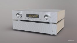
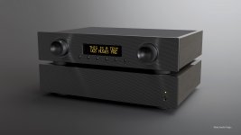
Thought I would share my design which I did last night for the original UGS Muses.
Found some inspiration while surfing the net. The ideas for the volume wheel will carry over for that smooth feeling, the rest is true to the UGS Muses.
Found some inspiration while surfing the net. The ideas for the volume wheel will carry over for that smooth feeling, the rest is true to the UGS Muses.
Attachments
Thought I would share my design which I did last night for the original UGS Muses.
Found some inspiration while surfing the net. The ideas for the volume wheel will carry over for that smooth feeling, the rest is true to the UGS Muses.
pay attantion if you want to use 2 OLED displays, the display will get bigger...
i think your rendering reffers to use only 1 display.
That is the plan, to use the Noritake VFD - added an orange effect since I want that (gel film)pay attantion if you want to use 2 OLED displays, the display will get bigger...
i think your rendering reffers to use only 1 display.
That front panel looks gorgeous! The 'gun barrel' gray set is beautiful.Thought I would share my design which I did last night for the original UGS Muses.
Found some inspiration while surfing the net. The ideas for the volume wheel will carry over for that smooth feeling, the rest is true to the UGS Muses.
The "gun barrel" gray is an effect of low light + backlight to show the display an power on led. So not an actual colorThat front panel looks gorgeous! The 'gun barrel' gray set is beautiful.
I'm still torn between using American Black Walnut or Ash.
Oneminde,
I'm wondering what the status is on this project, now that there seems to be a resurgence of activity (and GB) on the Algar_emi, UGS-muse preamp GB thread. I bought the PCBs for that preamp, and now I'm wondering if the few parts I have collected for your version, could be used on that project? I see you are fairly active on that thread as well. I'm new to both versions of the MUSE pre, and working through the BoM, to see what may be compatible. Would you provide the part #s for the Linear Systems, FETs you are going to use.
Since there's been no activity on this thread since late March, have you put your project on hold? Thx.
Well, the Muses Scion is more or less dead since the GB became active. I have paid for the new kit and its on its way as I am typing this. The new kit - for does who don't know - contain a custom Salas Shunt regulator and power supply. The option of using two (2) encoders. So, instead of using the original design as presented in the first post of this thread, I will use the newer design which you can see in #234.
The linear system FET's are the LSK170B and LSJ74B which can be found via the diyastore.
The status is that I am waiting for the boards (pcb), after that I need to collect all the components, build and test, once that is done, the chassis need to be manufactured. Lots of work. I will post updates sporadicly
- Home
- Source & Line
- Analog Line Level
- UGS MUSES Scion Preamplifier