X has suggested we run a thread for a useful circuit topology I have adapted from tube technology - the concertina phase splitter.
In tubes, we need two drivers for the AB/A output stage. These drivers must be in antiphase, since tubes are only 'n' type. We don't need this for a conventional pull push complementary output stage, since we have n and p types - ideal for a real world.
But there are situations in SS audio where power amplifiers require balanced drive. The first reason is the proaudio scene, where there are long lines all over a studio and usually strewn around with light cables, creating a hugely noisy environment. So balanced lines, if carefully configured, cancel this noise; this is a wonderful advantage and it relies on the two signals in antiphase. If both lines have the same noise induced into them, since the balanced requires antiphase signals the noise is common mode and is removed.
The simplest tube phase splitter is the single triode with equal loading in kathod and anode. Since current in the anode and kathod are identical, if these resistors are equal then the signal at the anode and the katod are also identical; just take the signal off through caps. This can be done with SS as well, and for even accuracy, you can use a complementary feedback pair.
I will post the schematic in within a couple of hours........ this can be used nicely with the Yarra to provide a balanced output.
Hugh
Member
Joined 2009
Paid Member
This appears to touch on some still common misperceptions about balanced interfaces. For one thing, balanced signal interconnection is distinct from differential (anti-phase) signaling/drive. In brief, balanced interconnection is in support of the rejection of common-mode noise. Differential signaling/drive is not required for common-mode rejection. Also, single-ended signaling can be utilized across an balanced interconnection with full common-mode noise rejection capability.
This topic is made clear in the Jensen Transformer AppNote AN-003.
This topic is made clear in the Jensen Transformer AppNote AN-003.

I do not like the idea very much: although the output impedances appear to be 10ohm, this is misleading.
The upper output is going to be normal and well-behaved, but any load or signal injected on the lower one will have an effect on the upper one, because the concertina acts as a common-base stage.
This will have negative effects for common-mode perturbations and common-load mismatches, something you certainly don't want for a line driver.
Better keep this circuit for its usual application of phase-splitter
Hello Hugh,
Some technical reason you don't use a device designed for that : THAT Corporation 1606/1646 OutSmarts Balanced Line Driver ICs ?
Cheers,
Marc
Some technical reason you don't use a device designed for that : THAT Corporation 1606/1646 OutSmarts Balanced Line Driver ICs ?
Cheers,
Marc


Phase splitting circuit
Hi
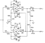
A while ago when I built my full bridge amp, I needed a phase splitting circuit that was accurate and didn't show phase misalignment as frequency rises, which happens if you use two op-amps, one inverting and the other non-inverting. These circuits have different parameters and properties.
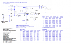
So came up with THIS discrete solution. Here is the circuit with descrete servos added. Both inputs can have a DC servo to zero the outputs for use as direct coupling if needed. Basically it is a balanced bridge circuit. If an input signal is given to +Vin, than the outputs will be exactly 180 out of phase. But the +Vout will be larger than -Vout. By loading down the +Vout more than -Vout, a deliberate misbalance of output current is created, causing the feedrward loop to create an error signal that makes up the missing gain on the -Vout side so that the two voltage outputs are equal in magnitude. This extra gain on one side is a trade off for output Z. So the output Z of -Vout is slightly larger than the output Z of +Vout but both output voltages are equal in magnitude and can be buffered by unity gain op-amps so the two outputs become equal but opposite phase.
Also there are integrated solutions such as a balanced line drivers like this.....THIS.
Hi
A while ago when I built my full bridge amp, I needed a phase splitting circuit that was accurate and didn't show phase misalignment as frequency rises, which happens if you use two op-amps, one inverting and the other non-inverting. These circuits have different parameters and properties.
So came up with THIS discrete solution. Here is the circuit with descrete servos added. Both inputs can have a DC servo to zero the outputs for use as direct coupling if needed. Basically it is a balanced bridge circuit. If an input signal is given to +Vin, than the outputs will be exactly 180 out of phase. But the +Vout will be larger than -Vout. By loading down the +Vout more than -Vout, a deliberate misbalance of output current is created, causing the feedrward loop to create an error signal that makes up the missing gain on the -Vout side so that the two voltage outputs are equal in magnitude. This extra gain on one side is a trade off for output Z. So the output Z of -Vout is slightly larger than the output Z of +Vout but both output voltages are equal in magnitude and can be buffered by unity gain op-amps so the two outputs become equal but opposite phase.
Also there are integrated solutions such as a balanced line drivers like this.....THIS.
Last edited:
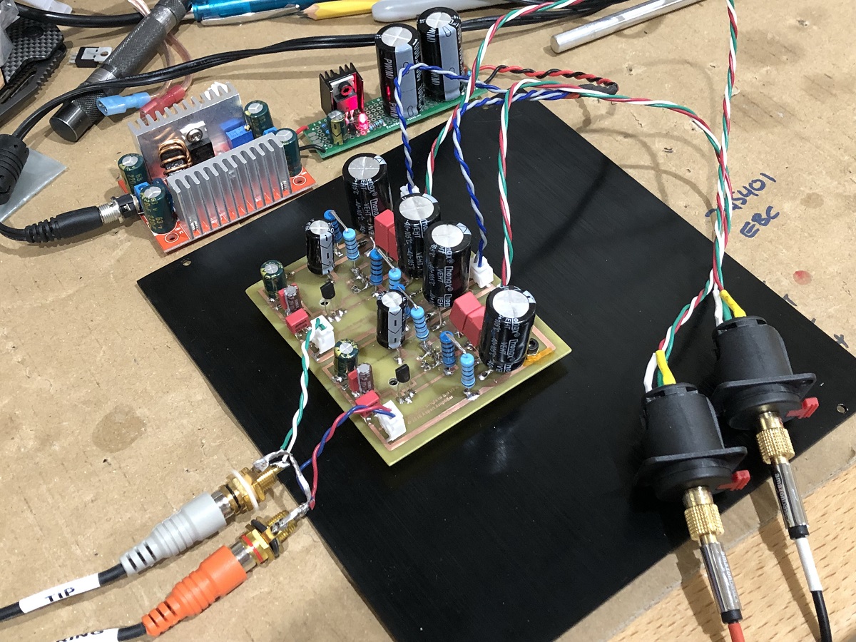
Why not use opamps etc? Well, they may be lower distortion, but they have lots of transistors and I don't think can be as quiet as an elegantly designed two transistor circuit. Hugh forgot that I took his two transistor CFP balanced line driver and made a balanced drive headphone amp out of it. It seems to drive a 49ohm load just fine and with a superb SE Class A harmonic profile. Do we really need 22 transistors and 0.00003%THD, or 2 transistors and 0.03%THD and a beautiful 2nd harmonic profile with descending higher orders?
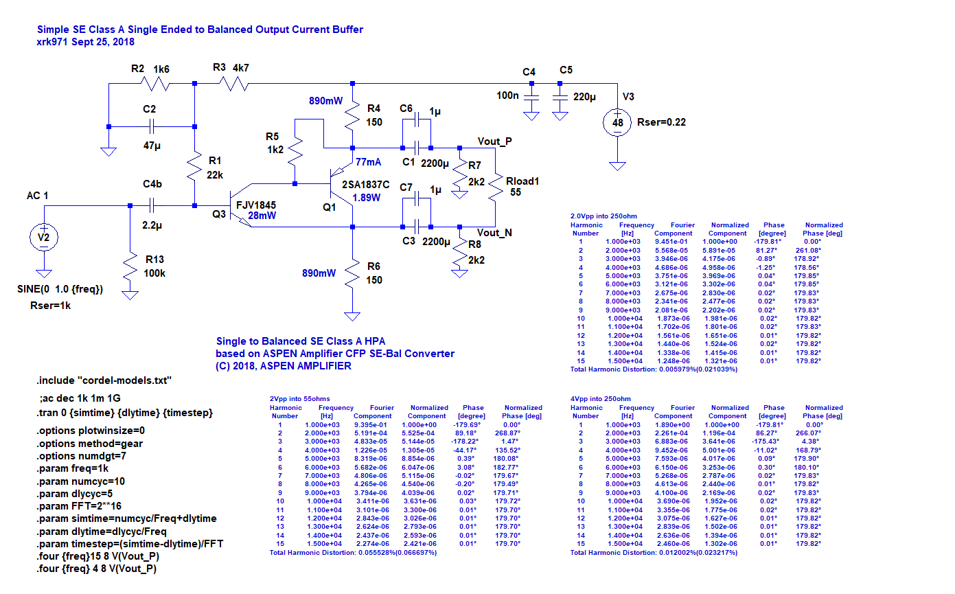
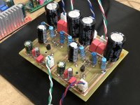
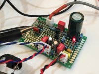
Running at 48v rails and 83mA bias current through a classic 2SA1837 makes for a nice headphone amp. If you used this to drive 600ohm lines, the THD would go way down:
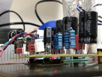
Hand etched PCB:
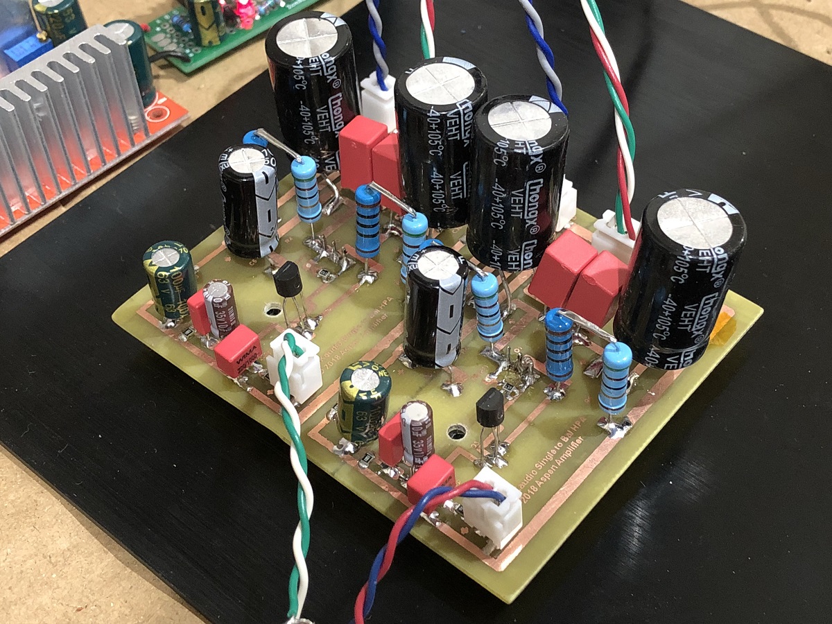
You can see the 2SA1837's underhung mounted here:

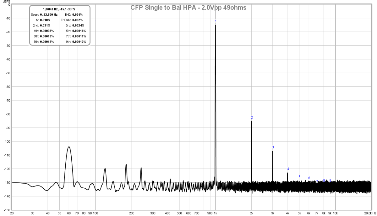
FFT for 2.0Vpp into 49ohm load, THD is 0.03%:
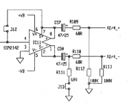
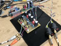
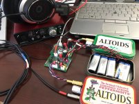
I also made a balanced drive headphone amp using the line-level version of the this circuit to drive a conventional SE Class A headphone amp (two of them, as left and right channels are used as +ve and -ve on same can):

Running at 48v rails and 83mA bias current through a classic 2SA1837 makes for a nice headphone amp. If you used this to drive 600ohm lines, the THD would go way down:
Hand etched PCB:
You can see the 2SA1837's underhung mounted here:
FFT for 2.0Vpp into 49ohm load, THD is 0.03%:
I also made a balanced drive headphone amp using the line-level version of the this circuit to drive a conventional SE Class A headphone amp (two of them, as left and right channels are used as +ve and -ve on same can):
Attachments
-
 SE-to-Bal-HPA-83mA-bias-2Vpp-49ohms.png83.6 KB · Views: 3,916
 -
 CFP-Bal-Amp-Build-02.jpg431.6 KB · Views: 3,744
 -
 CFP-Bal-Amp-Build-01.jpg430.2 KB · Views: 3,357
 -
 CFP-SE-Bal-HPA-Schematic.png145.3 KB · Views: 4,229
 -
 CFP-Bal-Amp-Build-03.jpg323.1 KB · Views: 3,138
 -
 Pocket-Class-A-Balanced-Drive-Test.jpg153.3 KB · Views: 1,814
Last edited:
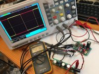
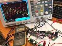
Here are some scope shots of the balanced line driver in action. Perfect mirror copies of ansignal from a single ended signal in. Square wave and music wave. All from two transistors!
Attachments
A simple way seen on a pro equipment.
A RCA single ended output, with a second output made from the single ended output with an Opamp in inverting mode gain: -1.
Simply adding 1 Opamp and 2 resistors.
Outputs, not directly to output connectors, but via 47 ohms resistors.
Another similar way is the "Birt" circuit.
At line level, this is good enough.
You mean like this (From ESP website):
Yes, but it uses an opamp. We want SE Class A output.
An externally hosted image should be here but it was not working when we last tested it.
Yes, but it uses an opamp. We want SE Class A output.
- Home
- Source & Line
- Analog Line Level
- Making balanced output from single end