Hi
I am sorting out a Revox B252, and having solved the power suplly issues (thanks Mooley), I am now addressing the fact that the right channel has no output, whereas the left appears to be OK.
Tracing the signal through has led me to the volume board, which has a pair of AD7528 dual buffered DAC which are "controlled" by a 4094 shift register.
The left channel DAC has signal input on pin 4, and output on pin18, the right has input on pin 4 but no output on pin 18. So logically I replaced the chip, and there was no change.
On Pin2 on the left there is no signal, however on the right on pin 2 there is a reduced signal present.
Checking the voltage to both chips, they both have 5v on pin 17.
On the left channel:
Pin 6 0v
Pin15 5v
Pin16 5v
On the right channel (bad)
Pin 6 5v
Pin15 5v
Pin16 5v
these are traced back to MCI14094B (IC701)and match the pins as follows:
Pin 4 to Pin6 (right ) 0v
Pin 5 to Pin 15 (right) 5v
pin 4 (IC703) to pin 16 (right) 5v
Pin 6 to pin 6 (left) 5v
Pin14 to pin 15 (left) 5v
Pin4 (IC703) to pin 16 (left) 5v
all of which leads me to believe that the right DAC is not being "switched" correctly (high on pin 6) and consequently no output.
so aside from replacing IC701, is there a way I can test why this is happening in case it is something upstream of IC701 that is causing it to hold pin 6 (IC701) high?
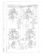
I have attached a block diagram and the 2 circuits of this part of the pre amp
I am not by any means, an expert on diagnosing logic, so any help is appreciated
Best
Peter
I am sorting out a Revox B252, and having solved the power suplly issues (thanks Mooley), I am now addressing the fact that the right channel has no output, whereas the left appears to be OK.
Tracing the signal through has led me to the volume board, which has a pair of AD7528 dual buffered DAC which are "controlled" by a 4094 shift register.
The left channel DAC has signal input on pin 4, and output on pin18, the right has input on pin 4 but no output on pin 18. So logically I replaced the chip, and there was no change.
On Pin2 on the left there is no signal, however on the right on pin 2 there is a reduced signal present.
Checking the voltage to both chips, they both have 5v on pin 17.
On the left channel:
Pin 6 0v
Pin15 5v
Pin16 5v
On the right channel (bad)
Pin 6 5v
Pin15 5v
Pin16 5v
these are traced back to MCI14094B (IC701)and match the pins as follows:
Pin 4 to Pin6 (right ) 0v
Pin 5 to Pin 15 (right) 5v
pin 4 (IC703) to pin 16 (right) 5v
Pin 6 to pin 6 (left) 5v
Pin14 to pin 15 (left) 5v
Pin4 (IC703) to pin 16 (left) 5v
all of which leads me to believe that the right DAC is not being "switched" correctly (high on pin 6) and consequently no output.
so aside from replacing IC701, is there a way I can test why this is happening in case it is something upstream of IC701 that is causing it to hold pin 6 (IC701) high?
I have attached a block diagram and the 2 circuits of this part of the pre amp
I am not by any means, an expert on diagnosing logic, so any help is appreciated
Best
Peter
Attachments
The CD4094 (IC702) is an 8 bit latching shift register used to set the DAC's input bits of both DACs I believe from what I can see. I guess (one or more of) its outputs are not getting to the right channel DAC.
With everything powered down buzz-out the connections on the 8 bit bus between the DACs and IC702. If the connections are OK, and the IC sockets are OK, one of the DACs must be faulty.
With everything powered down buzz-out the connections on the 8 bit bus between the DACs and IC702. If the connections are OK, and the IC sockets are OK, one of the DACs must be faulty.
Hi Mark
all the data lines are OK between IC 702 and both DAC's. I have already replaced the right DAC with a new AD7528, so I am presuming the DAC is OK-
the only difference I can see is on the faulty right channel, pin 6 (marked as DAC A (bar on top)/DAC B) is low(0v) and pin 15 (marked as CS (bar on top) is high, where as on the left good channel pin 6 is high and pin 15 is low
The AD7528 data sheet states for pin 6
DAC Selection:Both DAC latches share a common 8-bit input port. The control input DAC A/DAC B selects which DAC can accept data from the input port.
Further the AD7528 data sheet states that there two modes:
Mode Selection:Inputs CS and WR control the operating mode of the selected DAC. See Mode Selection Table below.
Write Mode:When CS and WR are both low the selected DAC is in the write mode. The input data latches of the selected DAC are transparent and its analog output responds to activity on DB0–DB7.
Hold Mode:The selected DAC latch retains the data which was present onDB0–DB7 just prior to CS or WR assuming a high state. Both analog outputs remain at the values corresponding to the data in their respective latches.
I have attached the 7528 data sheet which has the mode selection table.
Thanks again
Peter
Attachments
so some further analysis- I disconnected all the connectors to the volume board, thinking that is could be data from the microprocessor, or another board pulling something high or low- however the same result- output from pin 18 of the AD7528 on the left- which traces through to the output of the volume board, and thence to the main outputs, and no output from pin 18 on the right 7528.
the only difference I can see is that pin 6 on the left channel is 5v and on the right it is 0v, Pin 15 on the left is 0v and on the right it is 5v.
all the traces back to IC 701 and IC702 trace out as correct and have matching voltages.
so my current plan is to replace IC 701 and see if that is the problem. As far as I can figure it out the problem in on the volume board
any thoughts appreciated
So this has now got me very confused I see signal on pin 4- the inputs of both AD7528 DAC-IC101 and IC 201 on the volume board- I have replaced both of these and the shift store register IC701- all to no avail. The left channel works- the right channel does not. The only difference on the DAC chips, beside no output on pin 18 is that the CS (pin 15) is 5.17v on what I think is IC101 (left) and 0v on pin15 on IC201 (right)- however I have managed to confuse myself here as the schematic is unreadable and I think I have these right. The other pin (marked DACA/DACB) which is pin6 is 0v on IC101 and 5V on IC201. I have spent many hours tracing the circuit and checking continuity and the only thing I can find that appears inconsistent is on the supply output borad there is IC 702 (connected with sockets and 16pin flat connector cable- which tests fine)to a MC14094b shift/store register and IC701, another MC14094 which connects to the FET attenuators. on IC702 pin 15 is 5.1v, which comes over the connector cable (on the socket of which pins 15 and 16 are joined- so both 5.1v), however pin 16 which is marked as 5v on the circuit is only 3.3v. This same connection (from pin 16 on the cable) goes to IC101 through a 1k resistor to pin 15 and is 3.3v and to pin 16 which is also 3.3v Could this be the reason that the DAC is not getting the correct voltages, as I am assuming the the right channel DAC is not being "switched" inot the correct state for output. I am pulling the remaining few hairs from my head over this, and given I am no expert with logic chips- and assistance, guidance or other help is greatly appreciated thanks Peter
further tests
I found another thread describing the same symptoms, which was resolved by replacing the EPROM.
So I have a PC based scope (Quant Asylum 101b), which can do logic analysis- I am getting some micro grabbers and am planning to see if the EPROM is sending the right signal to the DAC.
Now it is a long time since I have done anything like this- so my knowledge is sketchy, and as I don not have a spare EPROM (though I do remember making some back in the day for Motorola 6800 CPU based systems (BBC Micro)- so if I can diagnose that it is the EPROM- then I have the not so simple task of finding another B252 with a working EPROM and making a copy of it.....
This is starting to feel like a saga...
- Status
- This old topic is closed. If you want to reopen this topic, contact a moderator using the "Report Post" button.
- Home
- Source & Line
- Analog Line Level
- Revox B252 Volume board issues