Looking at ways to improve my new NEC player i ran into these Technics schematics i was never aware of.Could you tell me more about these composite op-amps circuits? I don't have a clear understanding of what they do right now.
On the contrary..... You deliberately .... isn't the same thing.... ......
I thought you wanted "understanding". Sorry to have annoyed you at such great length.
Interesting how similar is the modified Sandman version to the Technics mods:
https://www.diyaudio.com/forums/analog-line-level/155143-class-aa-opamp-schematic.html#post1987545
It also confirm the need for two different op-amps unlike the Technics versions and in line with the original Best of both worlds paper too.
Now i found my real i/v stage: opa2132-lm6172 for pcm56 based player
Last edited:
Yes, I see my comment from 2009 just below jcx's post 'I fail to see the purpose of U2'
At least I can tell myself that I've made some progress!
A comment 7 years later at the end of the thread...
I am very curious what the second op amp does.
")
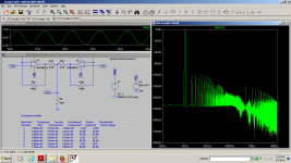
Just finished the composite class aa Technics version with opa2132 and lm6172 as i/v in a player i found in a scrap metal shop a while ago:
https://www.diyaudio.com/forums/digital-source/338152-nec-cd-810-revival-mods.html#post5809151
I can't measure it, I can listen to it though
https://www.diyaudio.com/forums/digital-source/338152-nec-cd-810-revival-mods.html#post5809151
I can't measure it, I can listen to it though
I wouldn't drive the LM with more than 23mA. With one or two op amps you can not drive a headphone properly.Here's the Technics headphone amp.
A2 is the load bootstrap amplifier and makes the headphone load (that's the 68 ohm and the actual headphone impedance) appear very high to A1, the main amplifier. With A1 seeing little or no load, the distortion is concomitantly low.
You could do this with 2 off dual LM4562 - 1 acting as A1 and the other three you parallel and form A2 for theoretical ppb distortion levels. IIRC the LM4562 can cleanly deliver c. 30mA so you will have close to 100mA to drive your headphones.
Its a pretty neat trick in my book!
I wouldn't drive the LM with more than 23mA. With one or two op amps you can not drive a headphone properly.
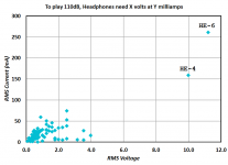
There's a nice table of electrical data covering 83 different headphones, over at head-fi.org link. They show the voltage (AC RMS) and the current (AC RMS) required, to make each pair of headphones produce 110 dB SPL (which is very loud). I plotted their data, below.
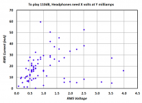
There are two "outlier" headphones which require vastly greater AC voltage and AC current, to produce 110 dB SPL: the HiFiMan HE-4 and HE-6, seen in the upper right corner of Figure 1. If we zoom in on the data for the remaining 81 headphones, the plot is Figure 2.
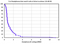
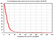
Figures 3 and 4 are plots of the cumulative distributions.
_
Attachments
 OT posts moved to:
 There's a nice table of electrical data covering 83 different headphones, over at head-fi.org link. They show the voltage (AC RMS) and the current (AC RMS) required, to make each pair of headphones produce 110 dB SPL (which is very loud). I plotted their data, below.
There are two "outlier" headphones which require vastly greater AC voltage and AC current, to produce 110 dB SPL: the HiFiMan HE-4 and HE-6, seen in the upper right corner of Figure 1. If we zoom in on the data for the remaining 81 headphones, the plot is Figure 2.
Figures 3 and 4 are plots of the cumulative distributions.
_
Very nice set of graphs, Mark
Either Spice is totally wrong, or I missed something .... Distortion is not better than using 2x opamp in parallel. So where is the benefit ?Here's the Technics headphone amp. Its a pretty neat trick in my book!
Cheers,
Patrick
Attachments
first of all you don't have equal value resistors, or even the schematics values, second you got the feedback from the wrong net. The bootstrap version is mainly even harmonics and lower!
By the way, i already built it into an i/v converter for my NEC player and it sounds very, very, very well! I'm going to build the same thing into my Denon player too.It's too good ! Technics knew their sh.t.
By the way, i already built it into an i/v converter for my NEC player and it sounds very, very, very well! I'm going to build the same thing into my Denon player too.It's too good ! Technics knew their sh.t.
Attachments
Last edited:
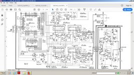
Except that this buffer was used in their best and most expensive products:When you study the Technics schematics, that's mostly disappointing. The quality in the 80's and 90's was below average at Technics.
slp-2000, slp1200, slp 1000, slp 999, slp 990, slp777 and probably some other that i won't bother to know, but these were sold over a decade period which tells a lot!
Please don't get me wrong! I never knew about this buffer until 2 weeks ago and i found them by looking for a schematic that would make a better i/v converter for pcm56. I never had a Technics cd player .
I have to thank the people here to point me in the right direction with the explanation for its functioning and i also thank EUVL for its spice directives
So i dared to build it and I'm so happy with the idea, that I'm going to replicate this buffer in any piece of equipment i intent to restore just because it works really well.
Now you couldn't think of a more emblematic schematic for this buffer than the slp-1000:
Attachments
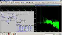
I only reproduced this circuit as i/v section for my NEC cd player restoration until now:
https://www.diyaudio.com/forums/digital-source/338152-nec-cd-810-revival-mods.html#post5809151
I have a tpa6120 based headphones amp so no need for other headphones amp soon.
I just hope that you won't take it as excessive talk on my topics...I'm just thrilled with the result and i simply showed faith to make it.I am not that guy that would disconsifder a Technics schematic because Technics isn't perceived as a high end manufacturer.I finished with this kind of thinking a while ago and i think i did very well.
I don't think Technics stole anything from Sandman...They probably worked together or had a different idea as Sandman circuit is a bit different.It might just be their own variation as Groner's circuit is a variation of the Burr Brown app .I don't think that Burr Brown will make a case about it claiming that Samuel Groner stole the Burr Brown bulletin and made use of it...
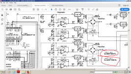
You can easily see in those schematics i mentioned that Technics used this circuit in I/v stage, line buffers, and headphones circuit eaqually well, so in bot inverting and non-inverting topology.
About this X stole the idea from Y...did you see any professional from Technics or Yamaha coming on this forum and telling : Technics stole my concept or Yamaha sold us the patent?
You will never see something like this here.They are professionals and they settle only after big money are payed if anything wrong.
https://www.diyaudio.com/forums/digital-source/338152-nec-cd-810-revival-mods.html#post5809151
I have a tpa6120 based headphones amp so no need for other headphones amp soon.
I just hope that you won't take it as excessive talk on my topics...I'm just thrilled with the result and i simply showed faith to make it.I am not that guy that would disconsifder a Technics schematic because Technics isn't perceived as a high end manufacturer.I finished with this kind of thinking a while ago and i think i did very well.
I don't think Technics stole anything from Sandman...They probably worked together or had a different idea as Sandman circuit is a bit different.It might just be their own variation as Groner's circuit is a variation of the Burr Brown app .I don't think that Burr Brown will make a case about it claiming that Samuel Groner stole the Burr Brown bulletin and made use of it...
You can easily see in those schematics i mentioned that Technics used this circuit in I/v stage, line buffers, and headphones circuit eaqually well, so in bot inverting and non-inverting topology.
About this X stole the idea from Y...did you see any professional from Technics or Yamaha coming on this forum and telling : Technics stole my concept or Yamaha sold us the patent?
You will never see something like this here.They are professionals and they settle only after big money are payed if anything wrong.
Last edited:
I hope you'll excuse me for this small offtopic that hopefully didn't ruin Groner's findings , but just because i dived into these Technics schematics i wonder if anyone saw the regulator sections and had any question about it.I never saw an op-amp regulating lm78xx before.These Technics "Anti high end" guys did it...
Attachments
- Home
- Source & Line
- Analog Line Level
- Samuel Groner's super opamp