Common guys, you can't be real!
It's 1991 Burr Brown app:
http://www.ti.com/lit/an/sboa002/sboa002.pdf
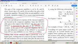
That version has far less low-frequency gain due to the local feedback around the second stage.
By the way, there was already a discussion about conditionally stable op-amps (monolithic, not composite) when I just joined this forum 16 years ago:
Opamp with open loop gain of 1,000,000,000,000,000.

Looking at the phase plot, those seem to have fifth-order compensation.
It's far older than that.
Yep, I think it's mentioned in books by Jerald Graeme from a very long time ago, and probably pre-dates that I am sure.
Samuel's paper was at least partially about the numerical optimization process they used to arrive at the compensation network values.
that gain in the second stage is supposed to multiply the slew rate of the input opamp .As A1 needs to have at least 2x the gain of A2 it's clear that setting a higher slew rate amplification will also lower the THD specs . Of course op211 doesn't need more slew rate, but with less expensive op-amps with good offset specs might be a good deal .That version has far less low-frequency gain due to the local feedback around the second stage.
that gain in the second stage is supposed to multiply the slew rate of the input opamp .As A1 needs to have at least 2x the gain of A2 it's clear that setting a higher slew rate amplification will also lower the THD specs . Of course op211 doesn't need more slew rate, but with less expensive op-amps with good offset specs might be a good deal .
You can't be serious.
What happened to jcx? I have not seen him around.
Gone where so many other good EEs with a passion for audio have gone over the years, I guess.
indeed..just reading the document, nothing else.You can't be serious.
indeed..just reading the document, nothing else.
Next time read more carefully and copy/paste between quotes instead of providing your own English-English translation.
As long as the input frequency f stays under certain limits following SR>>2*pi*f*Vpk, slew rate performance has nothing to do with THD. 50V/uS or 5000V/uS will provide at, say, 3Vpk exactly the same THD @1KHz or @10K or @100KHz.
SR does not get “amplified” or “multiplied” or anything like this. A2 simply lowers the output swing of A1 (which may as a result not enter into slewing limitations), then A2 (op amp with higher SR) provides the full output swing.
Last edited:
SR does not get “amplified” or “multiplied” or anything like this. A2 simply lowers the output swing of A1 (which may as a result not enter into slewing limitations), then A2 (op amp with higher SR) provides the full output swing.
Don't look back in anger! It might raise your blood pressure which may lead to more eyesight problems.
Attachments
Last edited:
Yep, I think it's mentioned in books by Jerald Graeme from a very long time ago, and probably pre-dates that I am sure.
Samuel's paper was at least partially about the numerical optimization process they used to arrive at the compensation network values.
Correct. They had to resort to some heuristic method to figure that one out. That's total voodoo for me ;-)
Jan
Don't look back in anger! It might raise your blood pressure which may lead to more eyesight problems.
The circuit "multiplies" the slew rate of A1 only by reducing its output swing, that's it. You still wouldn't be able to exceed the slew rate of A2 or anything.
I'm pretty sure that syn08 understands this based on his reply.
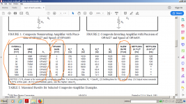
Calling it slew rate multiplication just doesn't make sense. The OPA603 has a slew rate of 1000V/us by itself. The composite amplifier in the app note is always lower than this if you check the table.
There's a lot of confusion about opamp slew rate. It is mostly determined by the (parasitic or comp) cap hanging off the internal gain node, and the internal current available to charge/discharge it.
How can that change when you wrap the opamp in a composite loop??
I suspect that in many of these app notes when they write slew rate they really mean rise time.
Back to topic. Anybody planning to build or measure any of these? I have a couple of spare adapter boards left. Say euro 5 including shipping?
Jan
Jan yes please! I wish to buy enough boards to build 3 composite opamps. Giving me the opportunity to make one unrecoverable error and still get a working stereo pair.
Sure, send me your address.
5 spoken for, 2 left.
Jan
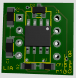
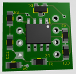
Here's the build info. As usual, the square pad is pin 1 of the DIL footprint. That also determines the top of the board when fitting DIL pins; the top also has the text 'Groner Comp OA'.
All parts are size 0805. Use MF for resistors, film caps for the comp and ceramic for the two supply decoupling.
Opamps are SOIC.
Don't forget to connect pin 1 to signal ground.
Jan
All parts are size 0805. Use MF for resistors, film caps for the comp and ceramic for the two supply decoupling.
Opamps are SOIC.
Don't forget to connect pin 1 to signal ground.
Jan
Attachments
Last edited:
@Jan, could you check the effect of adding(injecting) a small current into the output of the first opamp (e.g. forcing it into class A). It seems to mee that this could be an effective (additional) distortion reduction but also a GBW-control option, the configuration gives (me) the impression that the class-A effect may also be enhanced by the 2nd gain stage.
Hi Frans, I hear what you say, and I may do that when I get more time.
But note that the first opamp has a very light load and a very small (mV range) output level. For all intends and purposes it most probably never leaves class A as it is.
Jan
Frans, I checked the data sheet, and Iq is 3.6mA. Reasonable to assume that the output stage runs about half of that, 1.8mA bias. So as long as the output current stays below that, it remains in class A without any special measures.
With just mV's required, it will run in class A.
Jan
- Home
- Source & Line
- Analog Line Level
- Samuel Groner's super opamp