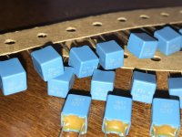
For the crossover filter caps, I initially went with a larger (wider) 5mm lead spacing, and think I'll change it out to the same narrow footprint as the opamp bypass caps. When I build it up, I'll likely use the following parts-
Wima MKP2C023301B00KSSSD CAP FILM 0.033UF 10% 63VDC RADIAL
or
Kemet R82DC3100AA50J CAP FILM 0.1UF 5% 63VDC RADIAL
Any thoughts? Either way I'm staying with the 5mm lead spacing.
Input caps (if desired) I'll likely use either-
Kemet R82DC4100AA60J CAP FILM 1UF 5% 63VDC RADIAL
or
Kemet R82DC4150AA60J CAP FILM 1.5UF 5% 63VDC RADIAL
or something similar. I may want to adjust the lead spacing to allow larger input caps, but I want to keep the scope of the PCB from getting to complicated, and thing I would rather stick to single footprints on most parts.
Last edited:
I would go with any mkp caps or even better the fkp ones(like FKP2C023301L00JSSD WIMA | Mouser ). r82 series are mkt , some will say that for audio mkt is not as good as the mkp . I personally use mkp 1837
for the 1uf i would use BFC247076105 Vishay BC Components | Capacitors | DigiKey or wima mks2 1uf
for the 1uf i would use BFC247076105 Vishay BC Components | Capacitors | DigiKey or wima mks2 1uf
Attachments
Last edited:
Digi-key is my preferred retailer, so looks like they have those there, price is good too when buying a couple dozen as needed for this project-
FKP2C023301L00JSSD WIMA | Capacitors | DigiKey
The MKS are a tad cheaper, but not much-
MKS2D031001A00MSSD WIMA | Capacitors | DigiKey
Those vishay 1uF do look good, maybe I'll take you up on your offer on six of them or so, assuming shipping is only a couple bucks") The Wima 1uF MKS is cheap too-
The Wima 1uF MKS is cheap too-
MKS2B041501E00JSSD WIMA | Capacitors | DigiKey
The Kemet caps should be okay for the crossover filter caps, but the coupling caps should be something better I suppose. Some have strong opinions regarding polystyrene caps, I'll reserve any judgement for now, and say simply that I may use them for an automotive application (noisy environment) of one of these boards
For home use I'll use the Wima FKP on mine
FKP2C023301L00JSSD WIMA | Capacitors | DigiKey
The MKS are a tad cheaper, but not much-
MKS2D031001A00MSSD WIMA | Capacitors | DigiKey
Those vishay 1uF do look good, maybe I'll take you up on your offer on six of them or so, assuming shipping is only a couple bucks
The Wima 1uF MKS is cheap too-MKS2B041501E00JSSD WIMA | Capacitors | DigiKey
The Kemet caps should be okay for the crossover filter caps, but the coupling caps should be something better I suppose. Some have strong opinions regarding polystyrene caps, I'll reserve any judgement for now, and say simply that I may use them for an automotive application (noisy environment) of one of these boards
For home use I'll use the Wima FKP on mine
Last edited:
Some opamps will not work properly without high speed decoupling from rail to rail, the 5532/34 for instance will not perform correctly without 0.1µF rail-to-railAny suggestions on opamp bypassing? Since I don't plan to use cranky opamps here I went with the oft-recommended (by datasheets at least) cap from each rail to ground. Should I put in the option to put one from rail-to-rail at each opamp as well?
decoupling, and distortion jumps well above published specs without this.
This is one reason while simply chopping and changing opamps in some random piece of equipment isn't as simple as some people think (others being input offset, output current capability, and phase margin)
Think it would be worth the effort to place the footprint for a rail-to-rail bypass on the board, maybe to be installed under the board, or an SMD perhaps under the opamp socket?
I'm not likely to need it, but if it makes it more versatile for potential users I'll incorporate it
I'm not likely to need it, but if it makes it more versatile for potential users I'll incorporate it
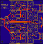
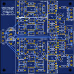
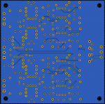
I'm working graveyard for two weeks (ugh) so have a little downtime at work to play some more. Renamed parts to new designations ("C" prefix for power caps, "CB" for bypass, and C*R/C*L for each channels filter caps) and added a pair of electrolytics between each filter opamp pair. Still need to rename a few things, rotate labels, etc. Should be about ready. I'll look it over for the next few hours and probably order a few to see how they work out.
Attachments
Last edited:
Thank youCommon misconception that circuits only work in the frequency range you want.
If you stick a Wi-Fi router next to your PCB, the PCB traces could unintentionally turn into nice little antennas/transmission lines. Previous EMC testing has shown me any interference above 2GHz easily becomes an issue even on the best PCB layout.
With bypassing requirements; power rail to ground next to each opamp supply pin is good, use 100nF ceramic and 10uF electrolytic or similar. Having capacitors (again 100nF and 10uF for example) every couple of inches between positive and negative supply rails can help. For example you could fit them in next to CB10, CB11, CB13.
The most important part is the power supply.
The power input must go through the smoothing capacitors then out to the audio.
This is due to charging impulses into the smoothing caps modulating the round line.
Do not mix in audio ground and power supply ground.
Just connect at one star point.
The power input must go through the smoothing capacitors then out to the audio.
This is due to charging impulses into the smoothing caps modulating the round line.
Do not mix in audio ground and power supply ground.
Just connect at one star point.
- Status
- This old topic is closed. If you want to reopen this topic, contact a moderator using the "Report Post" button.
- Home
- Source & Line
- Analog Line Level
- Crossover PCB in progress, ground plane or star/rail?