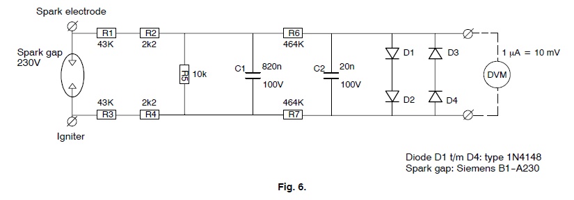
Does anyone know of an isolation opamp capble of 25kV voltage standoff? I have an application where I need to measure the voltage across a resistor in series with a spark plug via a spark plug "protection circuit" (see attached schematic) composed of a 150v plasma spark gap followed by a pair of 470k resistors and a CRC fiter, then finally by a pair of diode clamps. The circuit enables a regular DMM (like my Fluke) to measure the DC current across the 10k resistor when the spark is done firing. When it fires, most of the energy shunts through the SG, and the remaining is clamped by the diodes. The Fluke works fine. However, when I use an opamp or even a 1.5kV rated isolation opamp like ISO122, the spark kills the iso opamp. I tried an NJM5534D without the iso opamp and it fries too. They work for 4 to 5 seconds but the spark process is at 60Hz and lasts 3 seconds x 3 tries. How do they do it in a DMM front end? I need to amplify te voltage across the 10k resistor by 100x to get a decent range for the DAQ.
Any suggestions for HV rated isolation opamps are welcome - or perhaps someone can tell me how Fluke designs their DMM front ends to survive this kind of torture. I have some Broadcom ACPL-C87B's on order - they suppoedly can handle 15kV momentary since they use optical isolation vs capacitive isolation.
ACPL-C87B:
ACPL-C87B, ACPL-C87A, ACPL-C870 Precision Optically Isolated Voltage Sensor Data Sheet (1031 KB)
ISO-122:
http://www.ti.com/general/docs/supp...d=10&gotoUrl=http://www.ti.com/lit/gpn/iso122
This is the "spark protection" circuit used by Honeywell labs in NL:
Here is the above circuit implemented on verobord, note cutouts to prevent arcing:
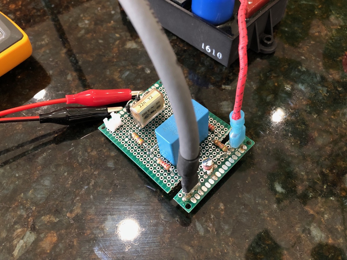
You can see the yellow Fluke 101 clipped to the output at the diodes (1N4007) and it works like a charm. However, try to connect an opamp and poof.
Any suggestions for HV rated isolation opamps are welcome - or perhaps someone can tell me how Fluke designs their DMM front ends to survive this kind of torture. I have some Broadcom ACPL-C87B's on order - they suppoedly can handle 15kV momentary since they use optical isolation vs capacitive isolation.
ACPL-C87B:
ACPL-C87B, ACPL-C87A, ACPL-C870 Precision Optically Isolated Voltage Sensor Data Sheet (1031 KB)
ISO-122:
http://www.ti.com/general/docs/supp...d=10&gotoUrl=http://www.ti.com/lit/gpn/iso122
This is the "spark protection" circuit used by Honeywell labs in NL:
Here is the above circuit implemented on verobord, note cutouts to prevent arcing:
You can see the yellow Fluke 101 clipped to the output at the diodes (1N4007) and it works like a charm. However, try to connect an opamp and poof.
Attachments

Last edited:
One obvious difference: the Fluke is floating so really measures the voltage difference across the 10k. But the opamp maybe has a connection to ground, possibly through the power supply, which may exceed the allowed voltage somewhere.
Interesting that you don't show the opamp circuit although that actually is the subject of the question ;-)
Jan
Interesting that you don't show the opamp circuit although that actually is the subject of the question ;-)
Jan
Last edited:
Hi Jan,
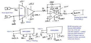
Thanks - I suspected this but was hopeful that all the protection circuit was going to bring all this down well below the 1.5kV rating on the ISO122, powered by a Murata NMV1205DC isolated DC-DC rated for 3kV. The Muratas were not damaged and continue to work.
Here is the schematic:
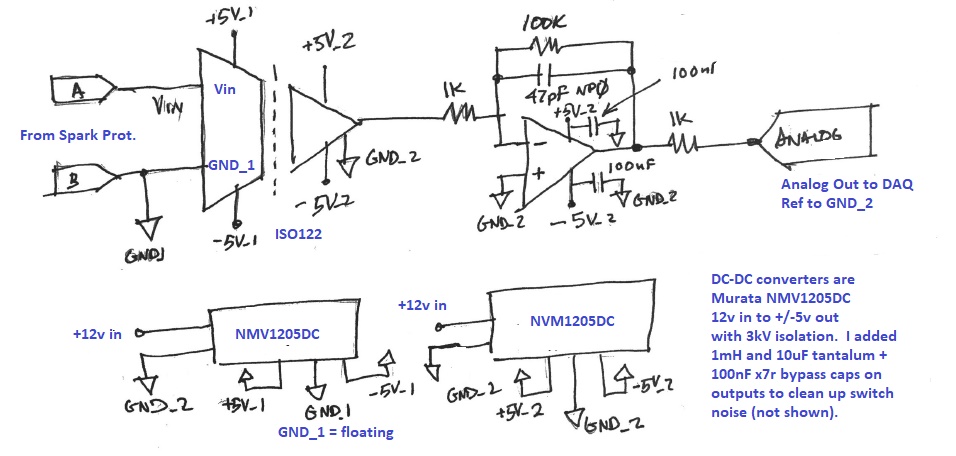
12v supply in is not connected to earth ground as provided via Class 2 12v wall wart isolation transformer.
Datasheet for DC-DC:
PDF | Murata Manufacturing Co., Ltd.
Maybe the fact that the Murata's lived (3kV) and the ISO122 died (1.5kV), brackets the leak through voltage at 1.5kV+ but less than 3kV? So maybe, the 15kV rated Broadcom ACPL will work out just fine?
Thanks - I suspected this but was hopeful that all the protection circuit was going to bring all this down well below the 1.5kV rating on the ISO122, powered by a Murata NMV1205DC isolated DC-DC rated for 3kV. The Muratas were not damaged and continue to work.
Here is the schematic:
12v supply in is not connected to earth ground as provided via Class 2 12v wall wart isolation transformer.
Datasheet for DC-DC:
PDF | Murata Manufacturing Co., Ltd.
Maybe the fact that the Murata's lived (3kV) and the ISO122 died (1.5kV), brackets the leak through voltage at 1.5kV+ but less than 3kV? So maybe, the 15kV rated Broadcom ACPL will work out just fine?
Attachments
Last edited:
So I have been thinking that maybe a keep it simple approach with a 9v battery powered isolated GND opamp can be used to measure the voltage and convert to a signal that lights up an LED. This is then optically coupled via a dark tube to a photoresistor (LDR) and that is simple loaded with a voltage as part of a divider and the analog voltage proportional to the LED gives me voltage at the opamp input. It would need to be calibrated but that’s not an issue. This saves having to find either a HV isolator opamp or HV isolated DC-DC power supply.
Some good tips here:
Project 145
Some good tips here:
Project 145
An externally hosted image should be here but it was not working when we last tested it.
Last edited:
I've gotten ~ 8 bit precision and ~ 10kHz bandwidth out of a standard NSC V-to-F and F-to-V converter pair. If that's good enough then you can build it with a fully floating power supply (2 x 9v) and use Fiber Optics for the 25kV isolation. V-to-F is an especially simple and robust analog-to-digital converter whose output is inherently serial. Perfect for Fiber optics. Or pulse transformers if you can find some that meet your isolation requirement.
So I have been thinking that maybe a keep it simple approach with a 9v battery powered
isolated GND opamp can be used to measure the voltage and convert to a signal that lights
up an LED. This is then optically coupled via a dark tube to a photoresistor (LDR)
If you are thinking of floating a 9V battery at a high common mode voltage, remember
that the battery's metal case is not isolated to that degree. In similar applications,
I've wrapped the battery in Kapton, and mounted it (so wrapped) with a plastic bracket,
on a suitable insulated mounting plate along with the circuit being powered.
Last edited:
The measurement you want to make is a high voltage across a resistor? There are different scenarios which might solve the problem.
Firstly, you don't have to isolate the voltage completely from the measurement device by an opamp. It's completely fine if the measurement device got separated ground and supply voltage. A very high impedance probe and a following voltage divider should be perfectly fine and does not pull down the voltage.
Secondly, you're not measuring a DC voltage, it's an impulse, square, triangle or more or less deformed signal shape. That means, an inductive coupling, galvanic separation (transformator, double-coil, etc.) of the voltage works fine while you stay within the corner frequencies of the transformator - at a spark plug you know very well the lower and upper frequency range (rpm).
Thirdly, a Wheatstone-Bridge or Wien-Bridge can be applied or used for a measurement with a lower voltage opamp.
And lastly, if you don't like any of these methods or got problems of their limits, you could build an opamp with tubes capable of the voltage.
Secondly, you're not measuring a DC voltage, it's an impulse, square, triangle or more or less deformed signal shape. That means, an inductive coupling, galvanic separation (transformator, double-coil, etc.) of the voltage works fine while you stay within the corner frequencies of the transformator - at a spark plug you know very well the lower and upper frequency range (rpm).
After the spark fires from a Direct Spark Ignition (DSI) module, it produces a circa 60vrms signal across the spark plug. If a flame is present, the ions in the flame plasma conduct current from the imposed AC excitation in one direction - thereby rectifying it and generating a DC flame ionization current of about 1uA or so. This is the basis of the safety mechanism for commercial burners to detect a flame or flame out - in order to shutoff the gas flow solenoid. I want to measure the flame ionization current that the DSI “sees”. The DSI gives a digital signal out as to the presence of the flame - but I want to measure the actual analog value.
That’s what the Honeywell circuit above does. I just want to be able to measure what the DMM measures and record it with a digital acquisition system.
So yes, it is in fact a DC signal. I only need maybe 3hz bandwidth - don’t care about the spark. We use clamp on inductive probes to monitor spark current if needed.
Last edited:
The old, old one from NSC that Bob Pease blathers about ... LM308 or something.
LM308 is the precision slow opamp, of course. LM331 is a currently-made V-F and probably ample for the purpose. I don't know if it is Pease's. (It looks more complicated than was possible when Pease was young.)
http://www.ti.com/lit/ds/symlink/lm331.pdf
Last edited:
Can the V2F’s provide the gain I will need to get a good voltage reading of a 1uA current across a 10kohm resistor? Or will I need to use a low noise opamp to first achieve the gain and then use the V2F? If using an opamp, I think driving the analog LED brightness and detecting the voltage change in an LDR might be a simpler and cleaner way of doing things. I do not need the bandwidth and in fact would like it low pass filtered to several Hz.
Hi Jan,
Thanks - I suspected this but was hopeful that all the protection circuit was going to bring all this down well below the 1.5kV rating on the ISO122, powered by a Murata NMV1205DC isolated DC-DC rated for 3kV. The Muratas were not damaged and continue to work.
Here is the schematic:

12v supply in is not connected to earth ground as provided via Class 2 12v wall wart isolation transformer.
Datasheet for DC-DC:
PDF | Murata Manufacturing Co., Ltd.
Maybe the fact that the Murata's lived (3kV) and the ISO122 died (1.5kV), brackets the leak through voltage at 1.5kV+ but less than 3kV? So maybe, the 15kV rated Broadcom ACPL will work out just fine?
The supply setup looks OK. But what is that Gnd_1 connected to??
Edit: forget it, it's the floating supply reference, I get it.
Jan
The BRoadcom ACPL-C87B works like a charm. I am using 9v battery and MC78L05 regulator for HV side. 12v linear wall wart and MC78L05 for the low side. Output goes to NJm5534D running on Murata +/-5v from same 12v source. The Broadcom is pretty slick as it seems to have its own dual rail DC-DC built in as it puts out two differential outputs and they can swing negative. Nice chip. As usual, care must be given for close and tight 100nf x7r bypass caps on Broadcom as it has switching and DA-AD going on internally.
Spark plug has no effect on analog voltage output and I can connect my IoT without fear now. Problem solved.
Spark plug has no effect on analog voltage output and I can connect my IoT without fear now. Problem solved.
The Broadcom ACPL-C87B works like a charm. I am using 9v battery and MC78L05 regulator for HV side. 12v linear wall wart and MC78L05 for the low side. Output goes to NJm5534D running on Murata +/-5v from same 12v source. The Broadcom is pretty slick as it seems to have its own dual rail DC-DC built in as it puts out two differential outputs and they can swing negative. Nice chip. As usual, care must be given for close and tight 100nf x7r bypass caps on Broadcom as it has switching and DA-AD going on internally.
Spark plug has no effect on analog voltage output and I can connect my IoT without fear now. Problem solved.
How much is that Broadcom?
Jan
If a DC-DC converter is rated 5kV. Can putting 3 in series give me 15kV?
Probably not.
Do you have specific reasons, or “probably not” just means your hunch? The rating is based on proof test at certain voltage of dielectric barrier. If you stack these in series, the voltage applied across dielectric scales same way that capacitors in series gain the cumulative voltages of the individual caps.
- Status
- This old topic is closed. If you want to reopen this topic, contact a moderator using the "Report Post" button.
- Home
- Source & Line
- Analog Line Level
- 25kV Isolated Opamp?