looking for a scheme - please give
kuly-s@rambler.ru
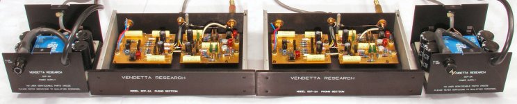
VENDETTA RESEARCH SCP-2A
tell me what transistors are their name
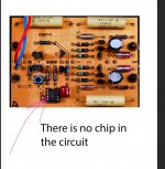
I found one on the Internet - but it does not fit - it is different in the photo there is a second chip in this circuit there is no chip
kuly-s@rambler.ru
VENDETTA RESEARCH SCP-2A
tell me what transistors are their name
I found one on the Internet - but it does not fit - it is different in the photo there is a second chip in this circuit there is no chip
Attachments
Last edited:
tell me wthere is a second chip in this circuit theil
hat transistors are their namere is no chip
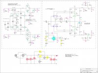
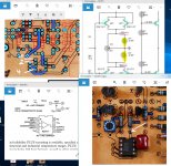
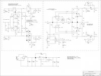
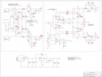
The IC is a DC servo, and is shown in the right half of the schematic..
Last edited:
there are two of them - and they are connected differently
Bear in mind that these are not official schematics. There is no official schematic, or service manual.
Also the transistors are no longer available (except for fakes).
hi !!! VER ----VENDETTA RESEARCH SCP-2A
Colleagues in the shop))) help tell me
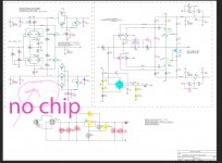
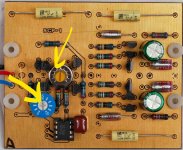
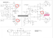
Where does the white arrow resistor fit --- to ground?
OR does it go to the foot of the chip then to which?
there are no circuits ----- approximately in an approximate circuit similar to these resistors hang in a pair on the ground
What are the values of these resistors-yellow arrow!?
Colleagues in the shop))) help tell me
Where does the white arrow resistor fit --- to ground?
OR does it go to the foot of the chip then to which?
there are no circuits ----- approximately in an approximate circuit similar to these resistors hang in a pair on the ground
What are the values of these resistors-yellow arrow!?
Attachments
Last edited:

I meant pin 6, not pin 7. my mistake
OK!!!
The main problem is that there are no real transistors (2sk147------2sj75,,,,,.
I don’t want to bet on the Chinese! --- I’ll search for a long time at the Japanese auction - and then it’s possible that they already sit there and sell goods from China - the truth is not known
I recently for an amplifier luxman-bought in China (real !!!!) transistors-original))))
Listening is not possible nasty nasty sound!
the graphics are good))) - but the music is different
Last edited:
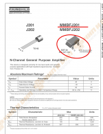
I suspect you can use 2sk170/ 2sj74, they are being used as low noise current sources to set the output voltage of the jfet cap multipliers, but you have to select ones with the correct idss to set the output voltage when combined with the resistors 5k11 and 4k99 ( or the resistors are selected to match the jfets idss) anyway it ‘s the combination of the jfets idss and the resistor value that sets the output voltage
The scheme turned on-the sound goes!
Applied other transistors-modes have changed and are not similar to the original. How do i fix skew 30mV-- 300mV. What can be leveled?
is 40mv in the left side ok?
The sound goes good plays well! help as you can adjust the scheme -modes?
please give good advice
Applied other transistors-modes have changed and are not similar to the original. How do i fix skew 30mV-- 300mV. What can be leveled?
is 40mv in the left side ok?
The sound goes good plays well! help as you can adjust the scheme -modes?
please give good advice
Attachments

Last edited:
- Status
- This old topic is closed. If you want to reopen this topic, contact a moderator using the "Report Post" button.
- Home
- Source & Line
- Analog Line Level
- Vendetta Research SCP-2A