I'm basically looking for a discrete unity gain differential amplifier topology (for converting a balanced signal into a single ended one - inputs need to be high impedance!). Has anyone dealt with a similar problem before?
Backstory:
I'm making a front-end for a combo mic/line/instrument input that gets fed into an ADC. Low-noise op-amps/instrumentation amps (<2.2nv √Hz) tend to be quite pricey, so I thought why not chuck my own together with 2N4403/2N4401's that I can get for a couple of cents each.
The solution I've come up with so far is basically 4 discrete op-amps, with 3 of them forming a unity gain instrumentation amplifier, with the last one performing up to +60dB of gain.
Why 4 op-amps and not 3 you ask, as in the case of an instrumentation amplifier? I'm using a digital potentiometer to control gain, and in order to avoid wiper distortion due to dynamic resistance, I've configured the last op-amp as a non-inverting gain stage. The wiper is connecting directly to the inverting input, which has something like 10+ meg ohms of resistance, so *fingers crossed*, the current through the wiper will only vary by a couple of uA.
It seems like a huge waste to use 3 DOAs to achieve, what is essentially, a differential to single ended buffer.
These are quite good, and easy to implement...
http://www.thatcorp.com/datashts/THAT_1200-Series_Datasheet.pdf
Mike
http://www.thatcorp.com/datashts/THAT_1200-Series_Datasheet.pdf
Mike
JFET source followers with CCS loads --> your favorite single opamp differential amplifier. If you worry about matching, just use a single opamp (not a dual) that has offset trim pins and don't bother matching the JFETs.
LSK170A Nchannel JFETs are low noise devices, sold in the diyAudio store. Run them at plenty of mA of bias current and drive low impedance resistive loads.
LSK170A Nchannel JFETs are low noise devices, sold in the diyAudio store. Run them at plenty of mA of bias current and drive low impedance resistive loads.
.....unity gain instrumentation amplifier, with the last one performing up to +60dB of gain.....
That does not make sense, unity gain THEN big gain. Assuming equivalent hisses, that's 3dB Noise Figure before you get well started.
I also suspect that your "high impedance" input does not need all the gain you might like on a Microphone. Also likely different connectors?
The hi-Z input needs low hiss current, not necessarily low hiss voltage. In BJT the two goals conflict; in FET you can find a good part to cover the impedance range you actually need.
I suspect this problem has been solved before, over and over. Plagiarize!
I'm basically looking for a discrete unity gain differential amplifier topology (for converting a balanced signal into a single ended one - inputs need to be high impedance!). Has anyone dealt with a similar problem before?
Backstory:
I'm making a front-end for a combo mic/line/instrument input that gets fed into an ADC. Low-noise op-amps/instrumentation amps (<2.2nv √Hz) tend to be quite pricey, so I thought why not chuck my own together with 2N4403/2N4401's that I can get for a couple of cents each.
The solution I've come up with so far is basically 4 discrete op-amps, with 3 of them forming a unity gain instrumentation amplifier, with the last one performing up to +60dB of gain.
Why 4 op-amps and not 3 you ask, as in the case of an instrumentation amplifier? I'm using a digital potentiometer to control gain, and in order to avoid wiper distortion due to dynamic resistance, I've configured the last op-amp as a non-inverting gain stage. The wiper is connecting directly to the inverting input, which has something like 10+ meg ohms of resistance, so *fingers crossed*, the current through the wiper will only vary by a couple of uA.
It seems like a huge waste to use 3 DOAs to achieve, what is essentially, a differential to single ended buffer.
I mean, you can do it with op-amps at a reasonable cost I would think. If this is some crazy-high volume product, it might be worth it but I don't see it. Your time designing these discrete op-amps isn't free, presumably. Also the PCB real-estate used is going to be much larger.
I guess if it's for personal / hobby use then anything goes.
")
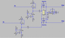
JFET source followers with CCS loads
Even cascoded with depletion MOSFETs.
Hi-Z, Low-inp-Q, high CMRR, selectable gain.
Attachments
Last edited:
+1. Mind you, getting ahold of schematics for commercial equipment isn't necessarily easy in this day and age...I suspect this problem has been solved before, over and over. Plagiarize!
But as a hint, you typically find Mic/Hi-Z or even Mic/Line/Hi-Z switches on such equipment. There's a reason for that.
Even combining a mic-in and a line-in is difficult.
You may need up to +50 dB for a mic, while handling line input levels in excess of +20 dBu may mandate +/-15 V supplies if your minimum gain is unity, and overall gain required may well be around -16 dB if we're assuming a 5 Vpp ADC input.
Doing the same for a Hi-Z + line input is a bit easier, as levels aren't too far off, but an extra buffer is still likely to be required. The input should be bothered by some common-mode components, as instrument cabling is generally unbalanced.
In order to come up with a good solution, you need to fully grasp the problem first. This thread is just another example of what happens when that isn't the case and people sort of try to jump in and tackle both in parallel.
Not to mention that having differential gain up front in a balanced input improves CMRR by equal measures.That does not make sense, unity gain THEN big gain. Assuming equivalent hisses, that's 3dB Noise Figure before you get well started.
You have to be careful though, unity voltage gain does generally not equate to unity power gain. You could have plenty of power gain by providing current gain alone. Of course the currents and devices required may well be insane, but this just illustrates how we can always trade off between voltage and current to match the devices available and external constraints.
Hi-Z input levels tend to be several hundred mV, and you want upwards of 500 kOhm or so of Z_in.I also suspect that your "high impedance" input does not need all the gain you might like on a Microphone. Also likely different connectors?
Mic cabling is XLR.
Hi-Z cabling is 1/4" TS.
Line-level cabling may use either XLR or 1/4" TRS / TS.
It is not uncommon to be providing both XLR and 1/4" inputs, with roles spread across them. Some concepts reserve XLR for the mic in order to keep contact issues from interfering with mic operation, with 1/4" for line-level / Hi-Z duties.
When deciding to implement combo jacks, pick them carefully. Random Chinese jobs are likely to have terrible handling for the 1/4" portion (I hate these suckers with a vengeance - either you can hardly get the plug back out or contact is terrible; at least the XLR portion tends to be OK).
Not clear what you want to invent.....
To convert a balanced signal to single ended, at line level, is usually done with this.
http://www.thatcorp.com/datashts/THAT_1240-Series_Datasheet.pdf
Or same from Texas Instrument and Analog device
INA137 INA134 http://www.ti.com/lit/ds/symlink/ina2137.pdf
SSM2143 SSM2141 https://datasheet.octopart.com/SSM2143SZ-Analog-Devices-datasheet-10720050.pdf
Find them with octopart.com
Last edited:
Why ?inputs need to be high impedance
How much ?
I have never seen a 0dB amp followed by a 60dB amp.
I'm building a digital snake box/recording interface with digitally controlled potentiometers for preamp gain control. I'm using combo XLR/TRS jacks. The TRS jacks are intended for line + instrument input (8k+ output impedance) and anything up to +22dBu. The XLR inputs have an input impedance of roughly 3k from the phantom power supply.
Basically, using digital potentiometers provides a very unique design challenge (noise, distortion and voltage ratings). The easiest way to insert them into an op-amp stage with minimal effects, is to use them in a non-inverting configuration as the feedback resistor. I'm OK with a small increase in noise - my gain stage is close to 1nv/hz in noise (in theory...), which is much likely smaller than the balanced to single ended stage. The challenge is very much finding a low-noise balanced to singled ended stage to make this topology work.
As another poster pointed out, maybe I'm solving the wrong problem or trying to solve too many at one time. I'm feeding anything from a few mV to something as large as +22dbU into the same input. I was planning to just amplify everything up to the rails and then have a static gain dump to interface to the ADC, as the noise impact of doing this seems quite minimal. I'm not even sure 60dB gain will be enough to hit the rails with a typical mic input.
A lot of interfaces I've seen have a separate mic/line/instrument switch to pad the input, so maybe I will start to look in that direction. This is only one piece of the puzzle!
Paralleling 5532's will drop the noise, its easy to parallel unity followers via 10 ohm
resistors. Two 5532's give you 4 opamps in parallel, nearly 6dB less noise which will
put you on 2nV/rtHz or so. Double this up for balanced input and drive a low impedance
differential amp gain stage.
So yes, 0dB followed by gain is exactly what you need for differential to single ended
conversion - without the high impedance inputs you can lose lots of CMRR as a differential
stage has different impedances on each input.
As another poster pointed out, maybe I'm solving the wrong problem or trying to solve too many at one time. I'm feeding anything from a few mV to something as large as +22dbU into the same input. I was planning to just amplify everything up to the rails and then have a static gain dump to interface to the ADC, as the noise impact of doing this seems quite minimal. I'm not even sure 60dB gain will be enough to hit the rails with a typical mic input.
Between 1997 and 2000 I built a recording device for a local radio station (Haarlem 105). The gain of its microphone preamplifier could be switched between 23 dB and 63 dB in 5 dB steps, the nominal level at the microphone amplifier's output was -10 dBV. That is, a -10 dBV RMS (so -7 dBV peak) sine wave would just turn on the first red LED of the level indicator, at -5 dBV (-2 dBV peak) a limiter kicked in and at 0 dBV (+3 dBV peak) the ADC was just driven into clipping.
In practice the reporters typically used it with a Sennheiser MD21 dynamic microphone, spoke into the microphone from about 30 cm (1 foot) distance, always used the 43 dB gain setting and usually hit the nominal level in the peaks. That is, someone speaking into a Sennheiser MD21 from 30 cm distance typically results in a peak voltage of -7 dBV - 43 dB = -50 dBV, or just above 3 mV.
Small-diaphragm condenser microphones are typically 10 dB more sensitive than a Sennheiser MD21, large-diaphragm condenser microphones are typically 20 dB more sensitive than a Sennheiser MD21. Besides, pop singers usually sing from much smaller distances than 30 cm, and maybe you also want to use the microphones for loud instruments like trumpets or drums. All in all, the microphone level can be just about anything.
By the way, do you intend to use the thing you are building for far miking with dynamic microphones? If so, it would make sense to at least try and keep the noise level at maximum gain below the thermal noise of the microphone. That's about 1.8 nV/sqrt(Hz) for a 200 ohm mike. With discrete bipolar transistors, that means using a relatively high bias current and devices with lowish base spreading resistance, with JFETs using high transconductance JFETs with low 1/f and G-R noise.
Last edited:
I've kind of given up on the unity gain differential buffer idea, and am essentially going to steal the THAT 1580/1583 architecture, but in discrete form. Their way of dealing with the digipot problem is to vary the feedback resistors with 2x digipots, instead of the Rg (gain) resistor. I thought this might reduce CMRR due to poor digipot matching... However, a useful property (that I completely forgout about) of the typical 3 op-amp instrumentation amplifier is that identical input signals are always reduced to unity gain from the gain stage, no matter the feedback resistor ratio. This means that the following difference amplifier is able to reject it at its full CMRR.
The THAT 1580/1583 architecture is also kind of unique, since it doesn't use a differential input stage. It instead uses a single input transistor with an inverting gain stage and current feedback. This necessitates the use of a blocking cap + DC servo, but I think the trade-offs for manufacturability + noise are worth it. You no longer need a matched input pair, plus the noise for a single transistor is 3dB lower than a differential pair (plus I already prefer a blocking cap to remove external DC offsets anyway).
I think I'm going to use a JFET as the input stage, since with instrument inputs the noise current from BJTs will make the noise figure pretty horrible. I do wonder if the open loop gain will be reduced/distortion will be increased in place of a BJT though. I'm thinking of using something like a 2SK880 or equivalent JFET - the noise should be under 2 nV/sqrt(Hz). I also want to test a bunch of other JFETs as well that don't have published noise figures. Ideally, I want to plug line/instrument/microphone/whatever into this thing and just have it work as a universal front end with a low noise figure.
In any case, it's annoying that one of the better (and commercial) solutions to this problem is "just use more digipots".
Last edited:
...The THAT 1580/1583 architecture is also kind of unique, since it doesn't use a differential input stage. It instead uses a single input transistor with an inverting gain stage and current feedback....
That's not how I see it. Input pair with differential NFB to both emitters. This was normally followed by a 4-R diff-amp; I see THAT proposes another path using their 5171 part.
You know TI has a whole mike/line preamp with digital control gain on a single chip? Made to drop into large consoles wholesale, reduce the ugly old analog to a minimum, while allowing a maximum of controls on the touch-screen.
Attachments
You have to analyze the differential amplifier circuit for input impedance - its not symmetrical. Driving it with low impedance signals isolates the inputs from these effects.Why ?
How much ?
I have never seen a 0dB amp followed by a 60dB amp.
For instance a differential amp with 10k resistors everywhere the common mode impedances are both 20k, but the differential impedances are 20k and 6.7k for non-inv and inv inputs respectively. And driven from a transformer (floating) sees 10k on each leg. Input buffering means the input impedances are uniformly high and the differential amp's asymmetry doesn't interact with the source.
If your differential amp is going to have variable input impedance, its even more of a good idea to pre-buffer the inputs.
- Status
- This old topic is closed. If you want to reopen this topic, contact a moderator using the "Report Post" button.
- Home
- Source & Line
- Analog Line Level
- Discrete Unity Gain Differential Buffer?