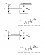
The LM4562 is very demanding. A decoupling difficult. I have attached an example. Local decoupling should not go to ground, but back to the star point. That does not seem to work in the case of the LM4562. Can someone explain this?
Attachments
Last edited:
In your diagram you said "Like a radio receiver, oscillates." What do you mean by that? I am curious about the symptoms of oscillation you got. Did you see the oscillation on a scope (if so, amplitude and frequency?), or did you hear something that you attribute to the Opamp oscillating?
I have to admit that I've never heard about "local decoupling should go back to the star point." It does not make sense, considering the purpose of "local decoupling," especially if the star ground is far away and the decoupling caps are connected to it by a thin long wire. Most application notes and discussions I saw talk about going to a ground plane as close as possible, which seems to be the configuration you found to not cause oscillation for you.
I have to admit that I've never heard about "local decoupling should go back to the star point." It does not make sense, considering the purpose of "local decoupling," especially if the star ground is far away and the decoupling caps are connected to it by a thin long wire. Most application notes and discussions I saw talk about going to a ground plane as close as possible, which seems to be the configuration you found to not cause oscillation for you.
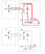
I see several chassis connections (one at the end of a wire to starpoint, one local at each amplifier). That spells ground loops and can easily lead to oscillations.
You should show a picture of the physical layout. Points at the same potential in a drawing seldom are in a physical implementation.
Jan
You should show a picture of the physical layout. Points at the same potential in a drawing seldom are in a physical implementation.
Jan
The LM4562 is a wide band, very high gain part - the 5534/32 has a much lower gain and the bandwidth is also much lower. You cannot get away with sloppy decoupling on modern high gain opamps.
As KCHANG has pointed out, running the local decouple ground back to the star ground means its no longer local decoupling. The trace inductance is about 15nH per CM so you quickly accumulate excessive trace inductance.
If your caps are not selected correctly, at HF (beyond the capacitor self resonance frequency) they are not capacitors anymore but inductors and hey presto you have an oscillator.
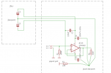
1. Don't run the local decouple traces all the way back to star ground - terminate all local decouple caps at the PSU ground trace right at the device
2. Make sure the decoupling is WIDEBAND - check out the data sheet. They will normally recommend 0.1uF to 1uF XR7 for local decoupling
3. With these new opamps (e.g. LM4562), its always best to use SMD for localized decoupling if you can - otherwise, use through hole, but make sure the leads are short.
4. Use bulk decoupling (22uF to 100uF) every few IC's
5. Don't mix up signal ground and PSU ground
As KCHANG has pointed out, running the local decouple ground back to the star ground means its no longer local decoupling. The trace inductance is about 15nH per CM so you quickly accumulate excessive trace inductance.
If your caps are not selected correctly, at HF (beyond the capacitor self resonance frequency) they are not capacitors anymore but inductors and hey presto you have an oscillator.
1. Don't run the local decouple traces all the way back to star ground - terminate all local decouple caps at the PSU ground trace right at the device
2. Make sure the decoupling is WIDEBAND - check out the data sheet. They will normally recommend 0.1uF to 1uF XR7 for local decoupling
3. With these new opamps (e.g. LM4562), its always best to use SMD for localized decoupling if you can - otherwise, use through hole, but make sure the leads are short.
4. Use bulk decoupling (22uF to 100uF) every few IC's
5. Don't mix up signal ground and PSU ground
The LM4562/LME49720 (same thing) are high-speed devices. They will oscillate if not properly treated. A good primer is Analog Devices AN-202:
https://www.analog.com/media/en/technical-documentation/application-notes/AN-202.pdf
https://www.analog.com/media/en/technical-documentation/application-notes/AN-202.pdf
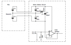
It is just the joke in the Elektor circuit not to put the capacitors to GND, so as not to pollute the signal ground. But right now I'm a bit confused.Using two caps (+G-) is going to be far more effective. They will act both from rail to rail and rail to ground.
This won't be of direct help to you, but rather than using a star ground, one way to avoid polluting ground with bypass cap currents is to use a four layer board and use two layers for positive and negative power, driven by wideband voltage regulators, with ground planes done as copper pours on the outer two layers. I have dozens of boards with LM4562 and even faster high speed amplifiers along with some 400MHz+ current feedback amps that are completely stable with no supply bypass caps directly on the supply pins. A large, unbroken PCB foil will have very low impedance, and allow you to use the minimum bypass caps required by the regulators.
Here's a useful fact that should convince you of the benefits of ground and power planes: a 1mm x 1mm square of 1 oz. PCB foil will have the same impedance (500µΩ) as a 50mm x 50mm square of 1 oz. PCB foil - the shape matters more than the overall size, and a super long, thin trace connecting a bypass cap to a star node will have a uselessly high impedance compared to a square.
In my circuits, I'm using the ADP7142 and ADP7182 regulators, and these require 1.5uF minimum output capacitance. I provide this with three 1uF 50V X7R 3216 sized bypass caps per rail, mounted right next to the regulators, and this works just fine. In this way, the bypass cap currents are low to start with, since the regulators make the supply impedance very low in the audio band, and the bypass caps are there mostly to make the amplifiers and regulators stable above the audio band. These bypass cap currents are therefore very low - the caps are there to make the regulators and amplifiers stable, not to actually conduct signal currents. The PCB foil and the regulators do the heavy lifting, and if you leave the foil mostly unbroken, the amplifiers will see very low power supply impedances, despite being physically somewhat far away from the bypass caps.
With amplifiers faster than 5-10MHz, you have to use RF design techniques. Star grounds are useless in that world and should be ignored. If you're concerned about currents inducing voltages in your ground system, consider balanced signaling. If your circuitry is 100% balanced, every time you send a signal to ground, there is always an equal and opposite current that it can be paired with in order to cancel both currents. Following this design concept, you have no star ground points, but instead, you have ground planes and power planes, and you can use high speed amplifiers with zero problems. Another benefit is that the power and ground planes act as really nice shielding. A balanced circuit done in this way will have random hum pickup that's only observable in an FFT even though the board is out in the open, outside of any enclosure.


- Status
- This old topic is closed. If you want to reopen this topic, contact a moderator using the "Report Post" button.
- Home
- Source & Line
- Analog Line Level
- LM4562, Decoupling, Starpoint, Noise and Oscillation