I was looking again for another low cost subwoofer bandpass board. I've already modified one and I was about to modify it again when I decided to see what else was available and roll the dice another time. My previous one is at Budget active subwoofer lowpass, buy, eval, mod and required substantial mods and I'm not entirely satisfied with it.
I noticed a board that had stereo pots on it") . Adjusting a 2nd order filter requires a stereo pot because 2 resistor values need to change at the same time. It also had enough caps to probably be a higher order bandpass and it's <$10 CDN delivered. Zero documentation is a standard for these products.
. Adjusting a 2nd order filter requires a stereo pot because 2 resistor values need to change at the same time. It also had enough caps to probably be a higher order bandpass and it's <$10 CDN delivered. Zero documentation is a standard for these products.
I noticed a board that had stereo pots on it
. Adjusting a 2nd order filter requires a stereo pot because 2 resistor values need to change at the same time. It also had enough caps to probably be a higher order bandpass and it's <$10 CDN delivered. Zero documentation is a standard for these products.Attachments
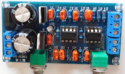
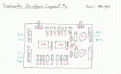
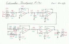
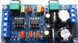
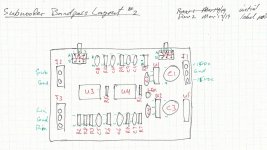
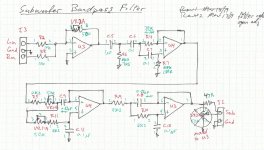
Layout and schematic
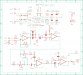
So here's the layout and schematic. All vanilla filters.
What's interesting is the one stereo pot is actually used to properly adjust a second order LP. The other stereo pot is sacrificed to volume control. The input summing circuit is also better than the previous one I tried. It comes with 12vdc regulators so I don't have to change them to use my +/15vdc supply. The volume control is unacceptable as the output impedance could be high and variable. Overall it seems alot better than the other model.
Attachments
Last edited:
Regulator issue
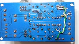
I powered it up and noticed a 2Vpp sawtooth wave @40Khz superimposed on the -12vdc. I thought it was the regulator so I replaced the LM7912 and same problem. Then I noticed the caps on the output were tiny (0.1uF) and lower than you usually use (> 2uF) so they (C2, C4 =2.2uF) got replaced and it fixed the problem. Its not a stuffing error, the silkscreen shows 0.1uf and its too small.
I powered it up and noticed a 2Vpp sawtooth wave @40Khz superimposed on the -12vdc. I thought it was the regulator so I replaced the LM7912 and same problem. Then I noticed the caps on the output were tiny (0.1uF) and lower than you usually use (> 2uF) so they (C2, C4 =2.2uF) got replaced and it fixed the problem. Its not a stuffing error, the silkscreen shows 0.1uf and its too small.
Attachments
First measurements
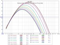
A few measurements to see if I need to change anything. I was surprised as its usable in stock form. There are some issues but it could be used as is.
Freq adj is independent of volume adj (unlike my other one). However it looks like the HP is crowding the LP because there's a knee near 30Hz and the amplitude increases a bit as you increase the cutoff point. It never reaches a flat top.
Attachments
Last edited:
HP changed to BW3
I changed the HP to a BW3 @ 20Hz. This flattens the low end of the curve alittle, and the higher end is still too rounded. There is a good filter calculator at Filter Design and Analysis that I used.
Changed resistors only R6=7K5, R4=39K, R7=180K.
I changed the HP to a BW3 @ 20Hz. This flattens the low end of the curve alittle, and the higher end is still too rounded. There is a good filter calculator at Filter Design and Analysis that I used.
Changed resistors only R6=7K5, R4=39K, R7=180K.
Attachments

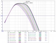
LP changed to BW2 + BW2
There are two 2nd order filters. One is fixed the other adjustable. With the current values they have Q=0.5 and I would prefer BW2 with Q=0.707. I would also like a flatter response when I change the cutoff freq.
Only needed to change two capacitors C8,C9 = 0.22uF. The fixed filter has been lowered to Fc=130Hz which is sufficient for me. The adjustable filter is now BW2 with adjustment range from 20Hz to 130Hz. At 130Hz the two filters becomes BW2 * BW2 = LR4.
Changed capacitors C8,C9 = 0.22uF.
Attachments
Last edited:
Those changes are correct. I'm happy with the filter and cut adjustment now.
There's nothing special in this circuit, is all vanilla, and it works. I only made a few component value changes and those should have been done in the factory and it would not have changed the cost.
I still have to fix the output impedance and gain adjustment. That's fairly straight forward but will require 2 track cuts. Then I'll post THD and noise. Stay tuned.
Last edited:
...The volume control is unacceptable ...
Attachments

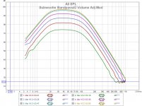
Vol adj and fixed output impedance
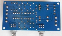
I cut two tracks to VR2a, and cut an island around the ground plane connection to its 3rd pin. VR2a pin#1 and #2 were connected so that impedance (and gain) increases when the pot is turned clockwise. R3 was removed and replaced by 2 wires to VR2a-1 and VR2a-2. VR2b was left untouched with all 3 pins still connected to ground.
A 47 ohm resistor was connected from U3-7 to Sub_out. All changes are on the board bottom.
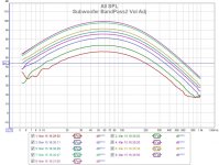
The modification provides gain=1 (0db) to gain=10 (+20db). The measured results are below. It's now exactly what I wanted. Beer time.
I cut two tracks to VR2a, and cut an island around the ground plane connection to its 3rd pin. VR2a pin#1 and #2 were connected so that impedance (and gain) increases when the pot is turned clockwise. R3 was removed and replaced by 2 wires to VR2a-1 and VR2a-2. VR2b was left untouched with all 3 pins still connected to ground.
A 47 ohm resistor was connected from U3-7 to Sub_out. All changes are on the board bottom.
The modification provides gain=1 (0db) to gain=10 (+20db). The measured results are below. It's now exactly what I wanted. Beer time.
Attachments
Last edited:
Doc update
Updated docs with all changes applied.
Updated docs with all changes applied.
Attachments
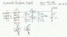
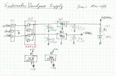
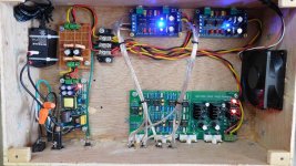
PS filter and 2nd board added
My +/-15VDC SMPS had too much residual switching noise so I added a 4th order power filter @fc~500Hz. The module's on board linear regulators (LM7x12) have sufficient PSRR to reject the remaining LF ripple. When I short the filter module inputs, and power up my amp, the speakers are silent.
I also required a 2nd subwoofer BP board as I needed to independently control 2 subwoofers. The second board has the same modifications as the first.
I did have an unexpected problem with the total supply capacitance causing the SMPS to limit inrush current and power cycle a few times at start up. So input supply caps of all 3 modules were replaced with smaller 1000uF caps. These boards were originally intended to rectify AC and I provide DC so less input supply capacitance per board is not a problem.
There is also a low speed quiet cooling fan added to provide air cross flow. The output air is cold, and the fan speed will probably be reduced some more or maybe even turned off.
Attachments
Just ordered this board...looks just what I need. Thanks for writing up your findings. I shall implement your mods if I may!
Is there any mileage in bypassing the onboard psu and feeding it something 'better'. I have a spare Studer 900 clone here that gets some good feedback here i wondered about using. Albeit it is about 10 times the size of the subwoofer board we are talking about here!
Is there any mileage in bypassing the onboard psu and feeding it something 'better'. I have a spare Studer 900 clone here that gets some good feedback here i wondered about using. Albeit it is about 10 times the size of the subwoofer board we are talking about here!
Thankyou for reply. It will make life easier using the onboard psu obviously.
This is a board I purchased earlier this year for the same job.
Sub Active Filter Crossover Board, SubWoofer PCB, Auto Power ON by moutoulos ™ | eBay
It is quite a bit nore involved and so for now I shall try 'your solution.
This is a board I purchased earlier this year for the same job.
Sub Active Filter Crossover Board, SubWoofer PCB, Auto Power ON by moutoulos ™ | eBay
It is quite a bit nore involved and so for now I shall try 'your solution.
Hi DonVK,
Thanks for helping me out.
1)- connect R7 to IC1B +ve , not gnd: Corrected, will post a revised schematic once I move both LP/HF filters on a single chip.
2)- OpAmp IC power connections are missing: The power connections are not available at the schematic level but are connected using name command and available at the Board level.
3)- it would be better to have both LP filters on the same OpAmp IC2 and both input HP filters on the same OpAmp IC1 (my pre-bought board mixed them): Should I replace IC2A with IC1B?
- Status
- This old topic is closed. If you want to reopen this topic, contact a moderator using the "Report Post" button.
- Home
- Source & Line
- Analog Line Level
- Budget active subwoofer lowpass #2, buy, eval, mod