Just asking, Why is your design using relays for input switching ? A natural property of the NSL32SR3 is to exhibit more than sufficient input isolation when the anode no longer receives current.
Suggest you should make use of this to achieve contact-less input switching- hence the relays are not needed at all.
Suggest you should make use of this to achieve contact-less input switching- hence the relays are not needed at all.
Just asking, Why is your design using relays for input switching ? A natural property of the NSL32SR3 is to exhibit more than sufficient input isolation when the anode no longer receives current.
Suggest you should make use of this to achieve contact-less input switching- hence the relays are not needed at all.
Good idea for MkIII
")
If I reset the parameters to default also the calibration is stuck on step2.
Upon resetting power unit showing error 21: LSE power failue.
When adjusting bias and updating params to actual values the error disappears but calibration not progressing.
Also observed in adjust bias mode, the measured resistance slowly drifting down below 700K as time progresses and upon restart of unit and immediately checking bias showing above 700K and drifting down. Is this normal or what could be wrong with any specific parts especially the SMD mosfets?
Seems to be the LDR are fine and no issues but calibration not progressing in step 2 looks like some issue with Nano and its ability to compute the values properly.
Thanks
So nano computes just fine for everyone else only fails for you and you deduct it must be nano? Maybe we should all replace our nanos or maybe even better you replace all your LDRs which you already reversed
I am only guessing that if all is fine the only thing left to check is my Nano board, that is the reason I just inquired if I should look into the Nano. But anyway I am going to replace all the LDRs and the SMD mosfets in couple of weeks time or so as my new parts will take sometime to arrive. I just hope this works as I just love the way this is designed and user friendly especially with the OLED display.
Thanks
Thanks
2K2 Resistor
Hello Ned, I am a confused about the 2K2 Resistors in your design. The pcb shows 6 positions for it, the BOM shows 6 position numbers but they only partly match. The BOM quantity shows 2.
Two of the positions on the pcb are underneath the arduino.
I guess, there are four needed on the pcb close to the trimmers, but are the two underneath the arduino needed?
Cheers
Ernst
Optocouplers
Hi again, I've almost finished the whole thing. One question I still have in regarding the LDRs. The dots on the LR have to match the dots on the pcb I strongly guess. When I look at your boards, all LDRs are orientated in the same way regarding there naming on top of the LDRs. In my case I have LDRs in both orientations. Is this ok?
Cheers
Ernst
Dot on the LDRs must align with Dot on the PCB (other letters on top of the LDR and their orientation is immaterial).
All LDRs are oriented in the same way (by aligining the Dot with dot on pcb)
Ensure this before powering up the unit.
Hi I am really interested in this in this setup but is there a schematic? I cannot seem to find one. Also I presume R+ D+ and A+ are the three 5VDC that you mention in the first post.
Unfortunately No schematic available....
Read post 1 and subsequent thread. ZDR developed this version direct on a PCB. This requires a nano board with specific chip and lot of customisations at hw/sw applied to it. Dont think you can take up this as a diy project from ground up without the modded nano/firmware and pcb with circuit.
Send him a PM for any available PCBs/Kits...
Thanks for the reply I do plan on ordering the kit ASAP just filling in parts needed with digikey.
Hi,
I added control over the wifi network to the preamp using the ESP-01 module (ESP8266).
The software running on ESP emulates the voltages sent by the TSOP34438 receiving signals from the the Apple Remote.
ESP generates voltages on pin GPIO2 (connected to the data pin of TSOP34438).
The ESP module connects to the WIFI network and listens to commands on port 80.
Example of sending "PLAY" button over the IP network (here from linux):
Connections:
3.3V PSU ______ ESP-01
3.3V <------------> VCC
3.3V <------------> CH_EN
GND <------------> GND
ESP-01 __________ TSOP34438
GPIO2 <------------> DATA
GND <--------------> GND
Source code (for the Arduino IDE) in the attachment.
I added control over the wifi network to the preamp using the ESP-01 module (ESP8266).
The software running on ESP emulates the voltages sent by the TSOP34438 receiving signals from the the Apple Remote.
ESP generates voltages on pin GPIO2 (connected to the data pin of TSOP34438).
The ESP module connects to the WIFI network and listens to commands on port 80.
Example of sending "PLAY" button over the IP network (here from linux):
Code:
$ echo "p" | nc -n <ESP_IP_ADDRESS> 80 -q 0Connections:
3.3V PSU ______ ESP-01
3.3V <------------> VCC
3.3V <------------> CH_EN
GND <------------> GND
ESP-01 __________ TSOP34438
GPIO2 <------------> DATA
GND <--------------> GND
Source code (for the Arduino IDE) in the attachment.
Attachments
Hi,
I added control over the wifi network to the preamp using the ESP-01 module (ESP8266).
The software running on ESP emulates the voltages sent by the TSOP34438 receiving signals from the the Apple Remote.
ESP generates voltages on pin GPIO2 (connected to the data pin of TSOP34438).
The ESP module connects to the WIFI network and listens to commands on port 80.
Example of sending "PLAY" button over the IP network (here from linux):
Code:$ echo "p" | nc -n <ESP_IP_ADDRESS> 80 -q 0
Connections:
3.3V PSU ______ ESP-01
3.3V <------------> VCC
3.3V <------------> CH_EN
GND <------------> GND
ESP-01 __________ TSOP34438
GPIO2 <------------> DATA
GND <--------------> GND
Source code (for the Arduino IDE) in the attachment.
Nice!
Need some help.
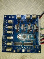
After everything assembled I´m having error 20.
No voltage on any of the 3 relays near LDR, but if I give them 5v directly they operate.
If I try to set bias, measure the ldr and try to calibrate it stop on step 19.
Sorry but, please can you tell me how to debug this to try to solve the problem.
After everything assembled I´m having error 20.
No voltage on any of the 3 relays near LDR, but if I give them 5v directly they operate.
If I try to set bias, measure the ldr and try to calibrate it stop on step 19.
Sorry but, please can you tell me how to debug this to try to solve the problem.
Attachments
![IMG_20190614_094803[1516].jpg](/community/data/attachments/692/692874-0cb278b51dc0fdcea1d679ee81c39c1c.jpg)
First of all, if you are getting any error at boot, this has to be cleared first as nothing else will work if errors are present. I have included a way to go around this error simply to allow to browse the setup menu and do measurements in different modes for troubleshooting purposes.
Three relays on the side are particularly critical as they are calibration relays. If you have no power on them, then you probably don’t have power on any of the relays as they are on the same power line. DC issues are easy to trace, just follow the voltage from R+ dc input.
Three relays on the side are particularly critical as they are calibration relays. If you have no power on them, then you probably don’t have power on any of the relays as they are on the same power line. DC issues are easy to trace, just follow the voltage from R+ dc input.
arduino
Hi Neb, I finished my build yesterday and tried to power it up today. I have the 1602 display and it showed just squares plus some strange letters or numbers. After a while letters stopped and there were just white squares.
I switched off the thing and reswitched it. Nothing at all.
Tried to flash the arduino, since I thought there might be something wrong. Followed your proposal but was not successful. Program found Arduino but couldn't connect to it. The system tried to connect for 10 times, then stopped. Strange. So I think I killed it with anything. Any idea?
I ordered a few of them for a new try.
Cheers,
Ernst
- Home
- Source & Line
- Analog Line Level
- LDR Pre MkII - LDR volume control and I/O switching