Cool. I like that a lot. Does it include a remote start for an amp with a trigger? I've got the boards, but haven't started the project yet.
Cool. I like that a lot. Does it include a remote start for an amp with a trigger? I've got the boards, but haven't started the project yet.
There is a connector which can control relay to turn on power amp. Amp is powered up by left or right encoder button (or holding play on remote for 3 seconds), turned off by left encoder button.
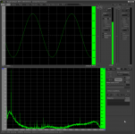
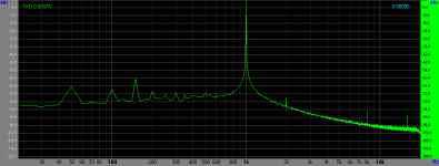
So far, the most accurate distortion measurement I could produce at worst case volume position, 35. Signal path: Scarlet 2i2>LDR Pre MkII>RMI-FC100>Scarlet 2i2. It's a non-calibrated measurement, which means it includes THD from amplifier and Scarlet 2i2, which are probably negligible anyway compared to LDRs.
Attachments
Last edited:
So far, the most accurate distortion measurement I could produce at worst case volume position, 35. Signal path: Scarlet 2i2>LDR Pre MkII>RMI-FC100>Scarlet 2i2. It's a non-calibrated measurement, which means it includes THD from amplifier and Scarlet 2i2, which are probably negligible anyway compared to LDRs.
Can you measure just the fc100 please and post in the appropriate thread?
Can you measure just the fc100 please and post in the appropriate thread?
I will try
")
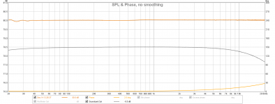
Cumulative frequency response, LDR Pre + FC100, volume at 35 (worst case scenario), 1W into 8 Ohm resistive. At first, I thought I was getting the same rolloff at 10KHz as some other measurements out there, but it was actually coming from Scarlet 2i2. After soundcard calibration, it's just boring flat. Or maybe I am doing something wrong
Attachments
Last edited:
Hi Neb
I'm putting the BOM together and I've got a Q re the wattage of the resistors for which no parts number is mentioned in your google sheet. Will the following values be OK? Reference is a Mouser part number.
220K metal film 1% 756-MFR5-220KFI 3/4W
500R metal film 1% 50PPM 71-RN55C-F-500 1/10W (Alternative would be 1/2W, 100PPM
2K2 metal film 1% 50PPM 279-H82K2FCA 1/4W
1K metal film 1% 660-MF1/4DCT26A1001F 1/4W
10K metal film 0,1% 660-MF1/4DCVTR1002F 1/4W
Thanks
ElEsido
Put a 470-1000uf 10v cap at 5v and gnd pins in the corner next to three relays.
Does this electrolytic cap is still required as not mentioned in the BOM on the new board which I recently got it? Can I leave it as it hinders the mounting hole of the PCB board.
Thanks
It depends on your display. Some of them inject noise in power line. Try without first.
Thanks, I am using the display to the link that is posted in the BOM. Hopefully it should work without this cap. Will try and power it and come back if this isn't the case.
Also, you should have a dedicated place for this cap on the board, close to ICs.
Hmm not sure if we are referring to the same cap. I was talking about the +5v and gnb cap value mentioned on the board near the power wiring option very close to the mounting hole. So I am confused when you say close to the ICs, as the ICs are on the other side of this cap.
I think you are referring to C30 marked as 470uf 10v electrolytic cap very close to the IC. So if its C30 you said like use anything from 470-1000uf 10v and I have a spare 470uf 63v cap which is fitting in this place. Can I use the same?
But on the extreme right there is another cap very close to the first relay which you have used on your build. I was referring to this cap and the value and if this is required to be used as I do not see the mention in the BOM.
Thanks
Last edited:
There was no place for C30 on the photo above, that was older board. That is why I used pins on the right. If you have place for c30, populate it just in case.
Oh ok got it now, yes I have your latest board as well now and will solder a 470uf 63v cap on C30 place and leave the cap near the extreme right of the mounting hole.
Thanks
- Home
- Source & Line
- Analog Line Level
- LDR Pre MkII - LDR volume control and I/O switching