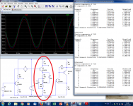
Are you referring to Elvee's circuit above? Note that this is two times the same circuit, one without the diode, one with the diode. This will enable measuring the distortion on the two collectors to compare the effect of the diode.
When building it you would only build the right side part.
Jan
When building it you would only build the right side part.
Jan

Ok.Probably about 500 ohms output impedance and ability to swing 4Vp-p and a gain of 4X.
Really there are only two basical ways:
1. Drop stage amplification via so-named local negative feedback. I.E. relatively increase emitter resistance.
2. Drop stage amplification via so-named global negative feedback
I’ld prefer to load CE stage to a current source, inverting connection and relatively high bias.
Note that both the textbook example I gave and the Kulish circuit do work, but they have major issues from a practical point of view: they are sensitive to loading. The diodes circuit will have the compensation upset if the load impedance significantly modifies the collector load.Thanks, I don't have big targets for this, I think anything below 0.1% is adequate.
I will try this one out and see how it goes.
Oon
The compensation with the Kulish will not be altered very much by loading, but the output impedance will need to be higher, because the ratio of resistors becomes unfavorable as soon as the gain is larger than 1.
This means that in practice, both circuits would require a follower, to eliminate the influence of the load on characteristics. With this in mind, it is better to act directly at the source of the distortion, the emitter circuit, rather than the collector circuit. Here is an example using a diode to compensate for the non-linearity.

With this sim, the THD improvement is only ~10dB, but that's simply because the compensation is not tweaked to the optimum. With a suitable compensating junction and resistor values, the compensation could be similar to the two other ones.
However, there is an even simpler solution: use a CFP composite instead of simple transistor: the improvement is >20dB, and importantly, it does not require matching or tweaking to attain that performance level (circuit 3). That amounts to negative feedback of course, but the topology remains simple....
...I used to use Spice 20 years ago in its more primitive state. ...I didn't know that it is now possible to simulate THD on it...
I use a version from 1999 (20 years old). The old-old SPICE .DISTO was notoriously bad and mine does not seem to offer it. It has .FOUR which computes THD, and with good agreement to pencil and breadboard if used properly. The Probe program has a FFT function which will find non-harmonic byproducts.
Here's 1KHz and 2.4KHz mixed 1:1 in FFT. We get products at 1k*, 1.4k, 2k, 2.4k*, 3k, 3.4k, 3.8k, 4.4k, 4.8k, 5.8k, 7.2k, 8.2k, 8.6k, 9.6k, 14.8k..... Roughly as expected, though 4.0k is not showing.
Attachments
Last edited:
Just try it!.The circuit and its gain formula are very simple.The gain formula is on the first page of one of the links in the photo.You have google too.Given the fact that you have an internal feedback you also have very high input impedance and should also have a bit lower output impedance compared with the naked common emitter. The audio electronics literature is full of simple and very good circuits that are ignored just because some other's big talk...More complex circuits doesn't necessarily mean better circuits too.Thanks for the advice.
Here it is again:Do you mind just posting the circuit alone. It doesn't seem to appear properly in your screen capture.
Attachments
Here it is again:
I just realised why, I was looking at it on the phone, it looks fine on PC.
Thanks.
Oon
- Status
- This old topic is closed. If you want to reopen this topic, contact a moderator using the "Report Post" button.
- Home
- Source & Line
- Analog Line Level
- Improvements on the common emitter amplifier