Hi,
I am looking for a simple circuit for a gain of about 4X. I am looking at a pure discreet design with no global feedback if possible. The easiest answer to this question is of course the standard common emitter amplifier. I am exploring if there is some way of reducing distortion by some simple ideas.
Addition of diodes or resistor or maybe cascode.
Thanking all in advance.
Oon
I am exploring if there is some way of reducing distortion by some simple ideas.
Dropout common emitter and use common base.
By definition a single stage cannot have global feedback, although it could be argued that the necessary local feedback is identical in all respects to global feedback. More than one stage almost always needs global feedback unless you are happy with poor performance.
The simple idea to reduce the gain of a BJT stage to x4 is local feedback. Some mixture of emitter degeneration and feedback from the collector will achieve what you want. You may need to include a follower too - depends on what this is supposed to drive.
The simple idea to reduce the gain of a BJT stage to x4 is local feedback. Some mixture of emitter degeneration and feedback from the collector will achieve what you want. You may need to include a follower too - depends on what this is supposed to drive.
...reducing distortion by some simple ideas.
Addition of diodes or resistor or maybe cascode.
Why not "addition of" transistors? They are hardly more expensive than diodes. You could pay more for a simple box than all the electronic amplification.
Here's a 5 minute jellybean design which gives pretty low THD.
If you want a *real* design, you need to specify input and output levels, impedances, supply voltage..... for all we know, you need to amplify 70V to 280V (say an electrostatic headphone booster) or a 1 Ohm load (ribbon speaker).
Attachments
Hi,
like PRR I´d suggest a CFP (complementary feedback pair) or Sziklai pair.
As the name implies it uses local feedback.
Like PRR´s circuit it may come in pure bipolar fashion or with a JFET master transistor as hybrid CFP or hybrid Sziklai. That would allow for simpler biasing.
jauu
Calvin
like PRR I´d suggest a CFP (complementary feedback pair) or Sziklai pair.
As the name implies it uses local feedback.
Like PRR´s circuit it may come in pure bipolar fashion or with a JFET master transistor as hybrid CFP or hybrid Sziklai. That would allow for simpler biasing.
jauu
Calvin
Interesting, and a emitter follower after that to bring down the output impedance.Dropout common emitter and use common base.
Oon
Just simple line level will do. I meant something simple in the sense working circuitry, addition of transistors sure, just not adding another 10s...Why not "addition of" transistors? They are hardly more expensive than diodes. You could pay more for a simple box than all the electronic amplification.
Here's a 5 minute jellybean design which gives pretty low THD.
If you want a *real* design, you need to specify input and output levels, impedances, supply voltage..... for all we know, you need to amplify 70V to 280V (say an electrostatic headphone booster) or a 1 Ohm load (ribbon speaker).
Oon
Just dropping in a sziklai will do the trick? Higher DC current gain will result in less distortion?Like PRR´s circuit it may come in pure bipolar fashion or with a JFET master transistor as hybrid CFP or hybrid Sziklai. That would allow for simpler biasing.
jauu
Calvin
Oon
....standard common emitter amplifier. I am exploring if there is some way of reducing distortion by some simple ideas....
What is wrong with no-NFB CE amp?
1) Gain approaches Vcc/0.030V, so at say 10V supply the gain can approach 300, which is more than the "about 4X" specified.
2) THD at maximum output approaches 26%, which while an exact THD goal was not specified is probably more than we want. THD is lower at lower output: 13% at half-max, 2.6% at tenth-max.
_THE_ way to resolve *both* problems is to forget this nebulous "global" buzzword. Use a high-ish supply. Add an emitter resistor.
Take a 48V supply. We can approach 16Vrms output @ ~~20%THD. We will probably expect more like 1.6Vrms, so 2% THD.
Gain naked approaches 1,000. Add emitter resistor to make gain more like 4X. The 250:1 reduction in gain makes 250:1 reduction in THD. 2%/250 is <0.01% THD which if simple is amply low for hi-fi.
Now we get to the stuff you are NOT specifying. Power consumption, do we care? Input impedance? Load impedance? Output impedance? Will it be driven from a tube? Will it be asked to drive one to eight power amps with NO change of gain? "Just simple line level will do" won't do.
The "simple" fix for output troubles is to run at high current. So power consumption is on the table. A simple BJT of practical hFE working at high current has low input impedance. (Emitter NFB helps but may not be enough until a *specs* are given and a sketch is made.) It comes down to a game of try more try less and find a best-fit to all the specs.
The 2-Q plan above is a dollar's worth of parts and will probably suit you. Why isn't it built yet? When we know what it doesn't do for you, we can suggest other strategies.
Maybe I should make myself clearer. I meant a standard textbook common emitter amplifier with a Rc/Re with a ratio of 4. I don't mean the naked version with emitter tied to ground. One possibility is i suppose probably to run the voltages relatively high, I suppose. Is that what you are suggesting? So with a voltage across emitter resistor higher then variations across Vbe will be reduced.
So you would suggest changing the standard npn with skizlai pair and that would reduce distortion?
Oon
So you would suggest changing the standard npn with skizlai pair and that would reduce distortion?
Oon
BTW PRR, you are saying that a common emitter amplifier with the emitter resistor can achieve a distortion figure of 0.01%? That's actually more than sufficient for me. I was expecting numbers approaching 0.5%.
How do do the distortion simulation. Is it a commonly available software. I would like to give it a shot.
Oon
How do do the distortion simulation. Is it a commonly available software. I would like to give it a shot.
Oon
> How do do the distortion simulation.
On my thumbs.
I asked the Idiot Assistant and it got similar numbers.
On my thumbs.
THD at maximum output approaches 26%,.... THD is lower at lower output: 13% at half-max, 2.6% at tenth-max.
Add emitter resistor to make gain more like 4X. The 250:1 reduction in gain makes 250:1 reduction in THD. 2%/250 is <0.01% THD...
I asked the Idiot Assistant and it got similar numbers.
Attachments
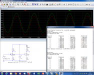
Using compensation methods, it is possible to further improve the distortion without resorting to feedback, be it global or local.
In this example, 2 diodes compensate for the non-linearity of the B-E junction, yielding a ~20dB improvement in THD. Why 2, when 4 should be needed because of the x4 gain? Because the I/V law of ordinary diodes is significantly less ideal than that of a transistor, meaning half the junction number is sufficient (depends on the exact diode type of course).
There are other ways to achieve the same result with a single diode in the emitter circuit and judiciously located capacitors, but taking into account the cost of a diode, the "diode-intensive" method is probably the best nowadays...
BTW, this was simulated with LTspice
Attachments
Last edited:
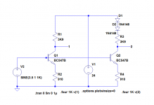
Here is the verbatim schematic.This is really interesting results and pretty much what I was looking for. But the image capture is not very clear. Did you put the 2 diodes at the collector resistor?
Note that in order to achieve 20dB correction or more, you will need to adjust the number/type of diode, and to extract the last 0.0001% you will need individual adjustment, for example with a trim resistor across one or more diode, to shunt a little current away, to arrive at the ideal correction law.
Attachments
Thanks for the advice. Will give that a shot. I am pretty familiar with the common emitter circuit, but kulish...how do you calculate gain, output impedance, input impedance etc.
Also how does it sound like. I actually try to avoid global feedback for a simple reason. I built a class A based on a sziklai combination however. It sounded harsher than a mosfet. I figured it probably because it has two stages. Probably has to do with the open loop gain having 2 poles now.
However the kulish looks more like a single stage. Tried to read up on exactly how it works. Not sure I understand >50%. Basically it seems the second transistor is becoming a pseudo current source, maintaining
The Vbe of the first transistor constant. Beyond that it gets a bit hazy.
Oon
- Status
- This old topic is closed. If you want to reopen this topic, contact a moderator using the "Report Post" button.
- Home
- Source & Line
- Analog Line Level
- Improvements on the common emitter amplifier