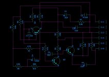
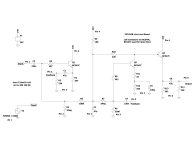
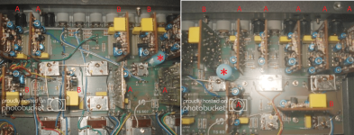
i managed to revers one of the board "as is" without much component placement to make it logic to understand.
dare to comment and identify the board in and outs ?
there must be an external feedback network or something as there is no logic in there imho.
transistors are BC338, all.
thanks,
dare to comment and identify the board in and outs ?
there must be an external feedback network or something as there is no logic in there imho.
transistors are BC338, all.
thanks,
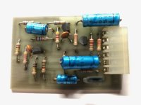
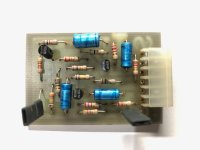
Attachments
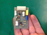
for the purpose of future searches
pin 1 in
pin 2 feedback
pin 3 GND
pin 4 +vcc (24vdc)
pin 5 feedback
pin 6 out
found out that there is no real limitation in upper frequency unit becomes really unstable above 30khz, lower cutoff is about 25hz....minimalist design, but it worked "ok" back in 1979 i guess. i upgraded all caps, will do the other boards and will test the whole unit soon on a Nikko 220
Hey pat allen, I too have a Rodec Mixmaster II which I'm fond of. Anything further with the schematics?
Most of my T-shaped slider knobs were cracked and chipped at their tops. I ended up placing a blob of epoxy broken tops and applied felt pads on the undersides to help them slide without scratching the faceplate.
Most of my T-shaped slider knobs were cracked and chipped at their tops. I ended up placing a blob of epoxy broken tops and applied felt pads on the undersides to help them slide without scratching the faceplate.
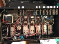
Some 30 years ago I acquired a Rodec Mixmaster II in disassembled condition. Someone had a go at servicing the unit. Turns out the master slider was jamming due to a foreign piece of plastic that got inside the slider body. A bitch to service but I managed to remove the offending plastic piece.
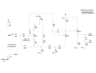
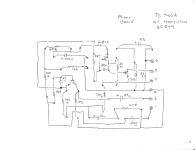
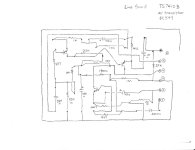
This appears to be an early version as none of the PCBs are silkscreened, and no markings as to where the 14 plugin modules go. Did some R-eng. There are two types of plugin module, marked as TS7410A which is a phono level amplifiers (qty. 9), and TS7410B which is a line level amplifier (qty. 5), Schematics are attached. Each module as connections for external passive components that make up level control and tone control circuits on buried on the motherboard. This may be an R-eng project for another day.
This appears to be an early version as none of the PCBs are silkscreened, and no markings as to where the 14 plugin modules go. Did some R-eng. There are two types of plugin module, marked as TS7410A which is a phono level amplifiers (qty. 9), and TS7410B which is a line level amplifier (qty. 5), Schematics are attached. Each module as connections for external passive components that make up level control and tone control circuits on buried on the motherboard. This may be an R-eng project for another day.
Attachments
Last edited:
- Home
- Source & Line
- Analog Line Level
- Rodec Mixmaster II info wanted