Finding cause of DC offset
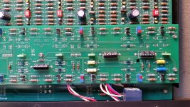
I am trying to find the cause of a very high DC offset on the high pass section of a Krell KBX crossover. Unfortunately no documentation is available. Any suggestions on how to proceed? I did fully recap the unit and the DC offset is still present without the frequency diving board installed (It was there before the recap as well).
I am trying to find the cause of a very high DC offset on the high pass section of a Krell KBX crossover. Unfortunately no documentation is available. Any suggestions on how to proceed? I did fully recap the unit and the DC offset is still present without the frequency diving board installed (It was there before the recap as well).
General rules:
1/ Always check supplies are correct. Very high offset could be a missing rail.
2/ If its opamp based then look at the DC conditions around each opamp and apply the rule of 'the opamp output will assume the voltage needed to bring the difference in voltage between the inputs to zero'.
3/ Look for any less obvious causes such as spillage or leakage from caps causing conductive areas on the PCB.
4/ Look for possible external circuitry 'pulling' an output outside what is correctable by the stage concerned... for example faulty muting circuitry.
Help identifying pot function
I am trying to figure out the function of some pots on a balanced Krell KBX crossover board. The transistors are MPS8099 and MPS8599, NPN/PNP pairs. Shown is the right channel only and the associated caps and resistors that determine the crossover frequency and slope (350 HZ 12 dB/oct). Any ideas?
I am trying to figure out the function of some pots on a balanced Krell KBX crossover board. The transistors are MPS8099 and MPS8599, NPN/PNP pairs. Shown is the right channel only and the associated caps and resistors that determine the crossover frequency and slope (350 HZ 12 dB/oct). Any ideas?
Attachments
 Multiple threads on the same topic merged.
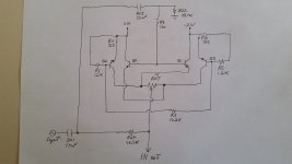
Re-Draw the circuit for "stupid eyes": power rails top and bottom, signal from left to right.
Yes, the pot is a DC offset between two emitter followers, one at +0.6V and one at -0.6V.
If you have more than a little offset with pot centered, something has a bad joint or is blown.
Yes, the pot is a DC offset between two emitter followers, one at +0.6V and one at -0.6V.
If you have more than a little offset with pot centered, something has a bad joint or is blown.
Attachments
I had this problem to on one of my KBX, problem a was broken Transistor due broken cap, causing a broken resistor.
So you have to check out the specific stage, all is balanced, thus you can get reference values of parts, so you can desolder some parts and do measurings of Res. and Caps and you have a way to find the bug.
Yes , lots of work and patience.
Notice, often the trimpots for setting DC make problems to, this means, make picture of the pot position, move it with a screwdriver, take original position and check out if corrosion caused the problem.
Good luck.
Frank
I figured out the function of all pots and how to adjust them. DC offset is under 1 mV on all outputs.
I modified the network board to work with my speakers so between that and normal drift of components over 30 years there was a lot of DC offset (over 100 mV) initially which varied with the attenuator position. This was due to offset from the network board being attenuated with pot position.
I modified the network board to work with my speakers so between that and normal drift of components over 30 years there was a lot of DC offset (over 100 mV) initially which varied with the attenuator position. This was due to offset from the network board being attenuated with pot position.
- Status
- This old topic is closed. If you want to reopen this topic, contact a moderator using the "Report Post" button.
- Home
- Source & Line
- Analog Line Level
- Krell KBX Crossover Info Needed