Hello Folks,
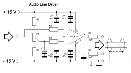
this Post is about optimal components dimension selection for a simple BUF634T Line Driver circuit (I do have a bunch of BUF634Ts here...), planned to drive about 4m of cable and connectors to a Power Amp. The driven Circuit is a balanced input terminated with 100kOhms (i.e. not an AES Input).
I'm asking, because I'm not experienced in optimal component values selection, but want to build this circuit as I know it works and heard myself that sounds well with lnger cables. The main issue for me is the Output Offset nulling circuit component values. Lateron, when the component values are set, I'm planning a board layout for three circuits per board which I can share if there's interest in it.
Here's the schematic:

Thanks a lot for your help!
Winfried
PS: I tried the search function but did not find sufficient advice...
this Post is about optimal components dimension selection for a simple BUF634T Line Driver circuit (I do have a bunch of BUF634Ts here...), planned to drive about 4m of cable and connectors to a Power Amp. The driven Circuit is a balanced input terminated with 100kOhms (i.e. not an AES Input).
I'm asking, because I'm not experienced in optimal component values selection, but want to build this circuit as I know it works and heard myself that sounds well with lnger cables. The main issue for me is the Output Offset nulling circuit component values. Lateron, when the component values are set, I'm planning a board layout for three circuits per board which I can share if there's interest in it.
Here's the schematic:
Thanks a lot for your help!
Winfried
PS: I tried the search function but did not find sufficient advice...
Attachments
Last edited:
Honestly a BUF634 seems rather overdressed for an application like this, even though it would obviously work. In your application you need neither its current output nor its bandwidth, slew rate (1% of that would be just fine) or very much capacitive load driving given your relatively short cabling, but would be burdened with manual offset adjustment and a fair bit of current draw.
What sort of maximum level is required? -0 dBu, +4 dBu, or all the way up to +22 dBu? What would the buffer be driven by?
Also, what do you consider an "AES input" (I don't assume we're talking about AES/EBU) and what role does input impedance play in relation to that? If you say "terminated by 100 kOhms" I assume that means an input with followers and 100 kOhms each?
You don't have to bias the amp, just a resistor to ground to allow input bias current. Something like 5 to 10k will work well; the lower, the lower the output offset, but the more it will load down the your source. If it is a 'normal' DAC or RIAA preamp even 2k will work well.
Then if your input signal might have DC, a coupling cap in series. That's all.
BTW They XLR pin 1 should NEVER be connected to signal ground, only to chassis ground.
Jan
Then if your input signal might have DC, a coupling cap in series. That's all.
BTW They XLR pin 1 should NEVER be connected to signal ground, only to chassis ground.
Jan
Hi Winfried,
50R & 100k =>0.05% - what kind of termination do you have? better than 1%
BTW: why 100k?...
Ulli
Yes, impedances should be as equal as possible to get good CMRR...The driven Circuit is a balanced input terminated with 100kOhms (i.e. not an AES Input).
50R & 100k =>0.05% - what kind of termination do you have? better than 1%
BTW: why 100k?...
What about Pseudo-Differential Cable:BTW They XLR pin 1 should NEVER be connected to signal ground, only to chassis ground.
An externally hosted image should be here but it was not working when we last tested it.
Ulli
Thank you Booth for your valuable Input!
Well, the Idea is top Substitute the current Output OpAmp which is a LME49740 with a more current driving capable output device. Actually the Unit I‘m kind of upgrading is a DEQX PDC-2.6p and the droben device is a power amp Board inside an active speaker.
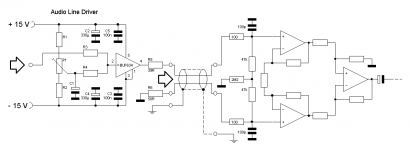
Let me post the schematic of the Power amp board Input section and we Go from there. Actually, as stated this is a custom interfacing, no XLR.

Hi Ulli,
Great to meet you here again, old buddy!
We had experimented with this driver circuit years ago... You then chose another drive circuit which turns out too costly for me, so I‘m reevaluating the BUF643
Thanks and Regards,
Winfried
Well, the Idea is top Substitute the current Output OpAmp which is a LME49740 with a more current driving capable output device. Actually the Unit I‘m kind of upgrading is a DEQX PDC-2.6p and the droben device is a power amp Board inside an active speaker.
Let me post the schematic of the Power amp board Input section and we Go from there. Actually, as stated this is a custom interfacing, no XLR.
Hi Ulli,
Great to meet you here again, old buddy!
We had experimented with this driver circuit years ago... You then chose another drive circuit which turns out too costly for me, so I‘m reevaluating the BUF643
Thanks and Regards,
Winfried
Attachments
Last edited:
What about Pseudo-Differential Cable:
An externally hosted image should be here but it was not working when we last tested it.
Ulli
Risky, not recommended, no need. The signal is carried between the two signal lines. In this scheme, any potential difference between the two units sets up a current through the screen which induces junk if the signal wires are not perfectly balanced, which they are not.
If, on the unbalanced side, you need to connect signal ground to chassis, use a small R to break any ground loop.
Jan
Well, the Idea is top Substitute the current Output OpAmp which is a LME49740 with a more current driving capable output device.
Winfried
When you drive that 100k with say 10V, that's a whopping 100uA signal current. Are you saying that the LME49740 is too weak to drive that??
Jan
Indeed. Assuming levels are sufficient as-is, I would just add the handful of components needed to convert the unbalanced output into an impedance-balanced one (i.e. take components between opamp output and output jack and replicate them between signal ground and cold, à la R6). This is assuming output impedance doesn't exceed 100-120 ohms, and it probably doesn't. Should work fine. At the same time, I'd be guessing that output impedance will be at least 47 ohms, and that should keep off maybe 600 pF of cable capacitance just fine. (If required, an increase would be trivial.)
So in the end a board with a handful of passives should do. If you're worried about shield currents, run that connection to the preamp case separately.
That input should have very good practical CMRR, limited only by matching of the 100p caps in the high frequencies. It would still be interesting to have an idea of input sensitivity (and noise) and whether there is an input level trim following.
Last edited:
> to drive about 4m of cable
13 feet cable, at 30pFd/ft, is 400pFd.
At 20KHz, 400pFd is 20K Ohms. 2K @ 200KHz.
Assuming 2V drive level, 0.1mA 20KHz, 1mA @ 200KHz.
It would seem that a very mild opamp would be ample for the work.
The BUF634 is an open-loop Diamond Buffer, and has large DC offset. Since that would upset your power amp, you must Do Something. Since the hi-mode input current can be 5uA to 20uA, either way, drift not specified, hi-R resistors and trims may not be wise. (They DO want you to use it *inside* an opamp NFB loop.)
In hi-mode the BUF Zout is about 1 Ohm. Your 39 and 50 "impedance balance" resistors should be like 39 and 40.
Personally _I_ would not bother with "balanced" to go a mere 13 feet, unless it was looped over fluorescent lamps or arc-welders. Nor would I take *any* gain after the line; better to run the line "hot" and pad-down as needed after. This path saves three opamps; a shame, but sometimes K.I.S.S. is the best plan.
You can get in trouble with unbalanced connections on <1 m - I know I have. [1] They may also work just fine over 10 m. If in doubt, certain characteristics of the devices you are connecting make a far greater difference than cable length.Personally _I_ would not bother with "balanced" to go a mere 13 feet, unless it was looped over fluorescent lamps or arc-welders.
[1] As have many other people when connecting gear from the studio realm to ordinary PCs. It's FAQ level common. Unbalanced connections and multiple IEC Class I devices just do not mix.
I would generally agree about higher levels, especially given a certain amount of extra noise introduced by balanced receivers (probably not so much in this case). In anything with an input level control, a balanced receiver of unity or low negative gain (like -6 dB) should do fine, with a fixed-level input I'd probably go with -12 dB to accomodate pro levels. Ultimately you've got a high degree of flexibility, depending on what sort of noise and distortion performance your electronics have - even more so when you're not bound to established level conventions. All a speaker really needs is maybe 110 dB of dynamic range, while electronics can hit close to 130 dB.
With all this input I'm thinking it may (despite having a bunch of BUF634s in the drawer...) be the right thing to use a real audio differential line driver like TI DRV134 (e.g. because of capacitive load drive capability).
Evaluations of this idea? Would this be the right or wrong track and why?
Regards,
Winfried
Evaluations of this idea? Would this be the right or wrong track and why?
Regards,
Winfried

....capacitive load drive capability... Would this be the right or wrong track and why?...
What problem are you trying to solve?
Don't connect the shield to GND at the left side (source side). Connect the shield to target side only! And make R5 and R6 equal.
P.S. Don't use sym. connections for local hifi devices (distance <1 meter). They are 2-3 dB noisier. The sym stuff was invented for studio use. They have to bridge e.g. 100 meter sometimes.
Last edited:
- Status
- This old topic is closed. If you want to reopen this topic, contact a moderator using the "Report Post" button.
- Home
- Source & Line
- Analog Line Level
- Audio Balanced Line Driver BUF634T