I have got a DIY tube preamp from my friend. It runs well without ground wire connected. But, when I use 3pin plug with gound wire connected in wall socket, the fuse immediately gets blown. Now I am running without grounding but I get electric shock when I touch the preamp. I don't have the schematic of the preamp. My friend who prepared the preamp failed to identify the cause. I have checked electric connection of my house including earthing, everything is ok, other electronic staffs are running well except the preamp. Can some please give some idea on what could be the possible reason.
Attachments
when I use 3pin plug with gound wire connected in wall socket, the fuse immediately gets blown.
Now I am running without grounding but I get electric shock when I touch the preamp.
This situation is very dangerous. Disconnect the unit and do not use it until it is repaired.
There is likely to be a design or construction error. Have it checked by a competent
electronic technician.
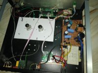
Yes, clearly your friend has made a serious error in making the preamp. In the picture above I cannot see a transformer for the high voltage supply; the power transformer seems to only have low voltage secondaries? Has he tried to connect the mains directly to a PSU board without a transformer?
There is a pair of thick wires (yellow/red) which seem to go from the mains switch, under the PSU board towards the small power transformer at the top of the picture, but then take a dive to the left and under the valve chassis/board. Where do they end up? I can't see another power transformer.
There is a pair of thick wires (yellow/red) which seem to go from the mains switch, under the PSU board towards the small power transformer at the top of the picture, but then take a dive to the left and under the valve chassis/board. Where do they end up? I can't see another power transformer.
The yellow wire has connected the small transformer which gives power to the controller of remote control. The main transformer is at the bottom right of the picture, it is ei core.
I have already unpluged it and taknig to a expert. Thank to all for your suggestion.
Just for interest, what is that little power board at the bottom - seems to take Mains AC from the fuse then send it to the transformer in the bottom right? The one with vacant positions for a bridge rectifier, 7805 reg etc.
That is a relay switch that takes 220 volt and powers the main transforme.
Just for interest, what is that little power board at the bottom - seems to take Mains AC from the fuse then send it to the transformer in the bottom right? The one with vacant positions for a bridge rectifier, 7805 reg etc.
That is a relay switch that takes 220 volt and powers the main transforme.
My guess is that a secondary (or if primary, life might have already been spilled) is led to chassi by one of the vero boards via a metallic standoff. So whole chassis is at potential. Once a mains connection with earth is used - bang goes the fuse. So at least in that sense it's correctly designed.
//
//
With due respect, but this is not a moment for Political Correctness, that whole project is a mess, but even worse, as mentioned above, a Death Trap.
Very complex, and by a very inexperienced builder, who can not even *solder*
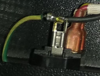
The most critical solder junction in the whole project , the green/yellow grounding wire, is NOT soldered, just look at the IEC terminal , the terminal itself was never hot enough to melt by itself solder alloy, solder was probably carried there already molten on the soldering iron tip and solidified by cooling when it touched the too cold terminal.
The classic definition of "cold solder".
That tells me the whole project is unusable and , being realistic, can´t even be "repaired", because this word implies something which "used to work but has now failed" which is not the case, this project was "born dead".
Please disassemble it and reuse whatever parts you can salvage for another projects.
Ladders must be climbed step by step, that´s what all of us did, there are no shortcuts.
You are very LUCKY (so far) you are not dead. Not kidding.
Plan B: do you want a tube preamp?
OK, get a preamp tube kit or even better a working board already assembled, no bells and whistles, just a properly working preamp, mount it there, reuse the cabinet/chassis and the power transformer and call it a day.
Main point is having a simple and easy to verify mains wiring setup, forget remote controlled turn on relays and such, just: properly grounded IEC socket > fuse (which you did NOT use, unless it´s inside IEC socket) > switch > power transformer primary ... PERIOD.
Everything properly soldered, of course.
As a side note: what can a competent Tech or Electrician tell you about this?
He´ll tell you the same as us, and what can he DO?
Only way to save this mess is to FULLY disassemble it (since not even soldered junctions can be trusted) and build something more reasonable inside, from the ground up (no pun intended).
Very complex, and by a very inexperienced builder, who can not even *solder*
The most critical solder junction in the whole project , the green/yellow grounding wire, is NOT soldered, just look at the IEC terminal , the terminal itself was never hot enough to melt by itself solder alloy, solder was probably carried there already molten on the soldering iron tip and solidified by cooling when it touched the too cold terminal.
The classic definition of "cold solder".
That tells me the whole project is unusable and , being realistic, can´t even be "repaired", because this word implies something which "used to work but has now failed" which is not the case, this project was "born dead".
Please disassemble it and reuse whatever parts you can salvage for another projects.
Ladders must be climbed step by step, that´s what all of us did, there are no shortcuts.
You are very LUCKY (so far) you are not dead. Not kidding.
Plan B: do you want a tube preamp?
OK, get a preamp tube kit or even better a working board already assembled, no bells and whistles, just a properly working preamp, mount it there, reuse the cabinet/chassis and the power transformer and call it a day.
Main point is having a simple and easy to verify mains wiring setup, forget remote controlled turn on relays and such, just: properly grounded IEC socket > fuse (which you did NOT use, unless it´s inside IEC socket) > switch > power transformer primary ... PERIOD.
Everything properly soldered, of course.
As a side note: what can a competent Tech or Electrician tell you about this?
He´ll tell you the same as us, and what can he DO?
Only way to save this mess is to FULLY disassemble it (since not even soldered junctions can be trusted) and build something more reasonable inside, from the ground up (no pun intended).
Attachments
Last edited:
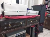
Thanks to all for your concern and suggestion, I have fixed the problem. It was an RCA jack thay was touching the chassis which is insulated and working perfect. As suggested I have disassembled and resoldered again for safety reason. Now no issue with fuze and electric shock, there is no noise or hum. I am using this tube preamp with FW M2 (DIY) and Jim Holtz's Finalist Speaker. Amazing performance, the preamp has around 22 db gain, but the 25 watt M2 is driving my 86 db speaker wonderfully. I used to use Hypex UCD 180 with a NAD preamp. Now probably these are not going to replace my present setup again. Thanks again.
Attachments
Last edited:
I don't see how that would solve your problem - I believe you may still have voltage going thru your chassis.
Also. you may want to check the DC blocking cap on your preamp out - the one that you fixed the ground - before you blow your amp. May wanna check the other preamp out DC Blocking cap too...
EDIT - Looks like you fixed the mis-wiring problem...good deal...
Also. you may want to check the DC blocking cap on your preamp out - the one that you fixed the ground - before you blow your amp. May wanna check the other preamp out DC Blocking cap too...
EDIT - Looks like you fixed the mis-wiring problem...good deal...
Last edited:
I don't see how that would solve your problem - I believe you would still have voltage going thru your chassis.
I don't think, I have thoroughly checked by myself. Only connect to the chessis is from the IEC socket ground pin to chessis. and a floating ground from input signal path (from RCA input) and chessis with a capacitor. Without this there is some hum. Is it ok?
Whoops, nevermind my previous post...
Yes...and please continue to use the 3 pronged power cord.......
Confused here...
Before I ever connect a DIY Preamp to an amp, I check for DC on preamp outputs...or potentially destroy the connected amp...
Only connect to the chessis is from the IEC socket ground pin to chessis
Yes...and please continue to use the 3 pronged power cord.......
floating ground from input signal path (from RCA input) and chessis with a capacitor.
Confused here...
Before I ever connect a DIY Preamp to an amp, I check for DC on preamp outputs...or potentially destroy the connected amp...
Last edited:
- Status
- This old topic is closed. If you want to reopen this topic, contact a moderator using the "Report Post" button.
- Home
- Source & Line
- Analog Line Level
- DIY preamplifier fuse gets blown when I connect ground wire