Hi folks
I obtained a pair of Toshiba TA7727P mono pre-amplifier ICs and built them into a stereo circuit based on the schematic in the datasheet.
Here is the schematic in the datasheet:
Here is how I adapted it for the TA7727P:
I didn't have the precise values for one of the caps and one of the resistors, I have marked these two changes in yellow, hopefully this will still work fine and the thing won't oscillate as a result.
Attachments
-
 TA7359P-Toshiba.gif14.1 KB · Views: 553
 -
 TA7727P-Toshiba.gif32.9 KB · Views: 404
 -
 TA7359P-Toshiba-6.gif86.3 KB · Views: 49
 -
 TA7359P-Toshiba-5.gif187.9 KB · Views: 262
 -
 TA7359P-Toshiba-4b.gif19.9 KB · Views: 59
 -
 TA7359P-Toshiba-4.gif89.3 KB · Views: 81
 -
 TA7359P-Toshiba-3.gif89.5 KB · Views: 59
 -
 TA7359P-Toshiba-2.jpg426.3 KB · Views: 197
 -
 TA7359P-Toshiba-1.gif136.4 KB · Views: 200
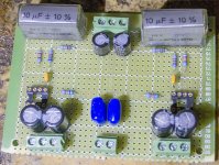
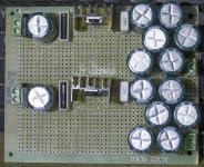
Here's what I've built. The big black electrolytics are Rubycon 100uF 25v, the small ones are Nippon Chemicon 33uF 25v. The big silver caps are Rifa CF 810 10uF 63V boxed polyester, the small blue ones are Konek MKT 1uF 100v dipped polyester. The little yellow ones are 0.1uF Vishay ceramic. Resistors are 0.25W metal film type.
Attachments
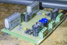
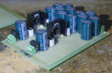
This is the dual 18v power supply I will power the Toshiba preamp with, it is a simple regulated type using a pair of L7818s and half a dozen Samsung smoothing caps, the circuit is the one shown in the L7818 datasheet with 0.1uF and 0.33uF polystyrene caps either side of the regulator.
Attachments
I still haven't been able to find any info on this IC beyond the datasheet, the sole mention of it I could find was in a list of TV spares from 1989 so I expect it was largely used in TV sets as a mono preamp.
I'm going to use the stereo preamp I have built as the input to a power stage to form an integrated amplifier. Not sure what form the power amp will take yet, maybe a chipamp.
I'm going to use the stereo preamp I have built as the input to a power stage to form an integrated amplifier. Not sure what form the power amp will take yet, maybe a chipamp.
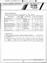
The one on the top right shows a gain of 20dB at 100Hz.Cheers, good to know.
Is the bass boost something you determined from the top two graphs on this page of the datasheet or something you know from experience?
But by the look of the feedback it's obvious (6k8 - 18nF).
Mona
The one on the top right shows a gain of 20dB at 100Hz. But by the look of the
feedback it's obvious (6k8 - 18nF).
Yes, and the gain is much too high for a line amp. It was for a tape head.
Delete the 6.8k and 18nF. Also reduce the 82k and increase the 100R.
Use values more like 20k and 2k for the nfb components. Then the 33uF
can remain the same.
Last edited:
NFB - Negative Feedback Network (components between pins 2 & 3)
As gain concerns. Try a small signal and hook to a headphone, then raise signal until You hear distortion.
As Rayma suggests, 20K and 2K would give You less gain.
Formulas here.
https://circuitdigest.com/calculators/op-amp-gain-calculator
As gain concerns. Try a small signal and hook to a headphone, then raise signal until You hear distortion.
As Rayma suggests, 20K and 2K would give You less gain.
Formulas here.
https://circuitdigest.com/calculators/op-amp-gain-calculator
Last edited:
Can't sleep and it's been bugging me so I took a look at the datasheet. Oh damn, it's not just a couple of pins wrong, all 8 are wrong, so I can't repair this circuit I've built, rather, I'll have to start over from scratch. At least I can probably salvage most of the components.
So, now the question is, is it worth bothering? Are these ICs good enough to warrant the effort or are they old, outdated crap that has been far surpassed by modern op amps?
BTW, note the error in the datasheet, which I circled in red, they have labelled pin 3 wrong.
So, now the question is, is it worth bothering? Are these ICs good enough to warrant the effort or are they old, outdated crap that has been far surpassed by modern op amps?
BTW, note the error in the datasheet, which I circled in red, they have labelled pin 3 wrong.
Attachments
Last edited:
Well, their layout is pretty much standard for a dual opamp in 8-pin DIP form. Same for the circuit, just make the changes Rayma suggested for a flat response and reasonable the gain. Nothing out of the ordinary there, so plenty of other opamps would work without mods. Redo it, and afterwards you can try others in place of the Toshibas if you're inclined.
I would leave the feedback resistors in a spot that's easy to get to if you want to experiment with small changes in gain, and if you're planning to use only one amp per package, I'd be inclined to load the second one instead of leaving it unconnected.
I would leave the feedback resistors in a spot that's easy to get to if you want to experiment with small changes in gain, and if you're planning to use only one amp per package, I'd be inclined to load the second one instead of leaving it unconnected.
Thanks for the advice Tim.
I have plenty of components to build a new circuit, but before I do I'll have to redraw the schematic of course, and also make changes to it to fit with Rayma's suggestions.
To use both parts of each opamp, wouldn't that require re-designing the schematic completely? Not sure I'm capable of doing that without mucho help.
I have plenty of components to build a new circuit, but before I do I'll have to redraw the schematic
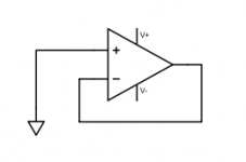
If you use only one of the pair, connect the unused op amp like this.
Attachments
To use both parts of each opamp, wouldn't that require re-designing the schematic completely? Not sure I'm capable of doing that without mucho help.
Nah, you could use one amp as a buffer (aka, unity gain voltage follower, very simple- look it up) and leave the rest as is (with rayma's changes). Just a couple more resistors or so. That might be helpful anyway if you're going to add a volume pot for preamp service.
If you don't want to go there, either connect the spare amps à la rayma, or just use one DIP for both channels and save the other one for later.
Last edited:
I really appreciate the help, clearly I need it!
I think it would be a useful learning process to have another go at using these ICs properly.
However, I think I'll put this project on the back burner for now and may revive it if I need an opamp based device sometime.
My main reason for doing this is that I am already working on other headphone amp projects and don't need another one just now. I don't need a preamp either as I already have a simple JFET based one I built a couple of weeks ago.
So thanks very much guys, I'll be needing your help when I return to this project.
I've removed all the parts apart from the two sockets, the resistors and the two ceramic caps, I've put them in a bag so I have them ready at hand for wen I decide to have another go at building them into a working device.
 Get some rest!
- Status
- This old topic is closed. If you want to reopen this topic, contact a moderator using the "Report Post" button.
- Home
- Source & Line
- Analog Line Level
- Toshiba TA7359P/TA7727P Pre-amplifier