Hey guys,
I'm required to design and build a graphic equalizer (15 band) which provides a +/-10dB boost/cut for each band across the audio spectrum
After doing alot of research I came across this Constant Q topology on sound whistles based off of the research paper(linked below). It posed some really nice advantages and simplicity compared to other topologies using the MFB band-pass filter.
I proceeded to derive the TF for the MFB band-pass filter (Didn't upload it as it's in a notebook...difficult to scan. It's correct though as I got the standard result)
I proceeded to design for the 15 bands for a Q of 4 and recorded my results in the excel sheet.
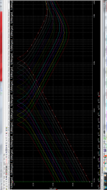
Following this I designed all the filters and simulated them and the response was exactly what I wanted, you can view them in the image shown below or in the Multisim file in the rar file(Filter Simulations). As you can see, there were no overlaps in the pass-bands of the filters.
After this I decided to integrate the filters with the rest of the circuitry as was done on sound whistles....and it worked...sort of. I simulated it for full boost and cut for alternating bands. Here is where I get confused(Oh btw sound whistles and the research paper didn't provide any circuit analysis so I went ahead and did it in the attached pdf. There you can see my analysis for boost and cut as well as the output of the Vu2a amplifier, based on the diagrams I provided. My lecturer said he thinks the 10 and 100 ohm values Rod had were probably an error and should be 10k and 100k, so I used 10k in my derivation.
Took the diagrams from here:
Eight Band Sub-Woofer Equaliser
Different project but same circuitry just the components were positioned a little differently.
Firstly this:
"There is one thing of special note in this circuit. R6 (39k as shown) determines the maximum amount of boost and cut, and if you wanted to, you can make it variable. With the filter circuits shown below, 39k allows a boost and cut of 12dB - which is about right in most installations. A value of 10k will allow a maximum of a little over 5dB. Any value between these limits will provide the optimum for a given environment, and this can be preset. This is a very useful feature, and one that I believe is unique to this circuit."
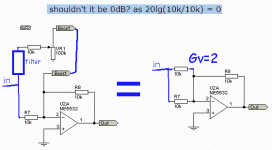
How does a value of 10k provide a gain of "A little over 5dB", shouldn't it be 0dB? as 20lg(10k/10k) = 0, I used the 25Hz test circuit located in the rar file as well to play around with the value of R6. 39k gives me about 13dB, 100k gives me 20dB(Makes sense), 31.6227766k doesn't give me 10dB(Gives me 12.3dB) however which doesn't make sense to me since 20lg(3.16227766) should give me 10dB. Using 10k does give me a little over 5dB as Rod Elliot said on sound whistles, which leads me to wonder, unless I've made a mistake in the circuitry in multisim, is it just based on tuning? Like do I just have to play around with this resistor value to get the gain I want?
Mathematically it doesn't make sense to me.
Okay that's that. So I decided to play around with the values of R6 in the Input Output Stage + Filters (2) file on multisim, a value of 39k gives me the 10dB value for full boost and cut for all the bands except the first and last band (25Hz and 16kHz) and I can't wrap my mind around why thats happening. Not sure where I went wrong.
Any Help would be much appreciated guys, Thanks in advance!
Research Paper:
https://pdfs.semanticscholar.org/3292/c31cdc4df5fdb09f55800c767be249930e89.pdf
Reference:
Expandable Graphic Equaliser
Note: All MS Files located in Zip Files

My analysis starts from Page 3 in the pdf. I modelled the pots as two resistors R1 and R2 whose values change based on the position of the pot.
I dont understand exactly from that equation I got in the end how that op-amp U2-B determines the overall gain of the circuit as stated in the original post.
Note the value A is = R6/R5
I'm required to design and build a graphic equalizer (15 band) which provides a +/-10dB boost/cut for each band across the audio spectrum
After doing alot of research I came across this Constant Q topology on sound whistles based off of the research paper(linked below). It posed some really nice advantages and simplicity compared to other topologies using the MFB band-pass filter.
I proceeded to derive the TF for the MFB band-pass filter (Didn't upload it as it's in a notebook...difficult to scan. It's correct though as I got the standard result)
I proceeded to design for the 15 bands for a Q of 4 and recorded my results in the excel sheet.
Following this I designed all the filters and simulated them and the response was exactly what I wanted, you can view them in the image shown below or in the Multisim file in the rar file(Filter Simulations). As you can see, there were no overlaps in the pass-bands of the filters.
After this I decided to integrate the filters with the rest of the circuitry as was done on sound whistles....and it worked...sort of. I simulated it for full boost and cut for alternating bands. Here is where I get confused(Oh btw sound whistles and the research paper didn't provide any circuit analysis so I went ahead and did it in the attached pdf. There you can see my analysis for boost and cut as well as the output of the Vu2a amplifier, based on the diagrams I provided. My lecturer said he thinks the 10 and 100 ohm values Rod had were probably an error and should be 10k and 100k, so I used 10k in my derivation.
Took the diagrams from here:
Eight Band Sub-Woofer Equaliser
Different project but same circuitry just the components were positioned a little differently.
Firstly this:
"There is one thing of special note in this circuit. R6 (39k as shown) determines the maximum amount of boost and cut, and if you wanted to, you can make it variable. With the filter circuits shown below, 39k allows a boost and cut of 12dB - which is about right in most installations. A value of 10k will allow a maximum of a little over 5dB. Any value between these limits will provide the optimum for a given environment, and this can be preset. This is a very useful feature, and one that I believe is unique to this circuit."
How does a value of 10k provide a gain of "A little over 5dB", shouldn't it be 0dB? as 20lg(10k/10k) = 0, I used the 25Hz test circuit located in the rar file as well to play around with the value of R6. 39k gives me about 13dB, 100k gives me 20dB(Makes sense), 31.6227766k doesn't give me 10dB(Gives me 12.3dB) however which doesn't make sense to me since 20lg(3.16227766) should give me 10dB. Using 10k does give me a little over 5dB as Rod Elliot said on sound whistles, which leads me to wonder, unless I've made a mistake in the circuitry in multisim, is it just based on tuning? Like do I just have to play around with this resistor value to get the gain I want?
Mathematically it doesn't make sense to me.
Okay that's that. So I decided to play around with the values of R6 in the Input Output Stage + Filters (2) file on multisim, a value of 39k gives me the 10dB value for full boost and cut for all the bands except the first and last band (25Hz and 16kHz) and I can't wrap my mind around why thats happening. Not sure where I went wrong.
Any Help would be much appreciated guys, Thanks in advance!
Research Paper:
https://pdfs.semanticscholar.org/3292/c31cdc4df5fdb09f55800c767be249930e89.pdf
Reference:
Expandable Graphic Equaliser
Note: All MS Files located in Zip Files

An externally hosted image should be here but it was not working when we last tested it.
My analysis starts from Page 3 in the pdf. I modelled the pots as two resistors R1 and R2 whose values change based on the position of the pot.
I dont understand exactly from that equation I got in the end how that op-amp U2-B determines the overall gain of the circuit as stated in the original post.
Note the value A is = R6/R5
Attachments
- Status
- This old topic is closed. If you want to reopen this topic, contact a moderator using the "Report Post" button.

