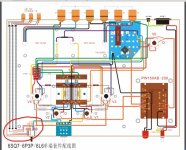
Building a headphone amp, I am a little bit puzzled about the signal routing from the PHONO and AUX cinch inputs to
the source selecting switch. Particularly the earthing and shielding connections.
For that purpose I studied the wiring picture of a design which is using two AUX and one CD cinch inputs and there my puzzling
started. Unfortunately I do not have the circuit diagram. From that picture and looking at the rotary switch on the left bottom side,
I concluded that there is a rotary switch used with two poles (A and C) and three positions, something like I give here.
AUX2,AUX2 and CD goes to position 3, 2 and 1 respectively, but how about those positions 7,8 and 9? where does the connections go to?
I do not see a separate signal return path. Those wiring connections are shielded and earthed at the cinch inputs.
Attachments
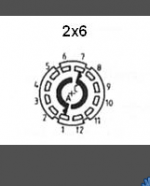
The switch makes or breaks the signal path, no return required as the ground is the screen, 7, 8 and 9 is the other channel if stereo.
Yes, of course 7,8 and 9 are the other positions for the other channel. I should have noticed this
 .
.But I do not know what you mean with "the screen", not those shields around the wires to the inputs I suppose?
Yes, of course 7,8 and 9 are the other positions for the other channel. I should have noticed this
But I do not know what you mean with "the screen", not those shields around the wires to the inputs I suppose?
Take another look at that drawing. The screens (=shield=audio-GND) of the three inputs are connected to each other at the RCA terminals (top left of the drawing), and to some point (white dot) on the blue PCB. I am pretty sure this "point on the blue PCB" is GND.
In other words: the audio-GNDs of all three RCA inputs are connected to each other, and to the audio-GND of the pre amp. This is a common way to hook up the audio-GND coming from the different input sources.
However, some will argue that connecting the different GNDs in this way is asking for trouble with ground loops. A way out would be to use another layer on the input selector and also switch the GNDs in the same way as the input signals.
- Status
- This old topic is closed. If you want to reopen this topic, contact a moderator using the "Report Post" button.