I've been working on a preamp which I discussed in this thread, I'm pretty much happy with the operation & performance now but I'm getting some pretty loud switching noise from the output relays (Omron G6SK) which is unaffected by the attenuator setting. All the other relays are of the same type and quiet even with the attenuator set to 0dB. The noise sounds the same for both make and break operations and DC on the outputs is around 2-300µV.
I'm scratching my head a bit on how to deal with this one... any ideas?
I've attached the part of the schematic with the relays on, the signals come straight from the switched attenuator.
I'm scratching my head a bit on how to deal with this one... any ideas?
I've attached the part of the schematic with the relays on, the signals come straight from the switched attenuator.
Attachments
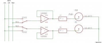
I'm getting some pretty loud switching noise from the output relays
Can you post the complete schematic, at least from the attenuator onward?
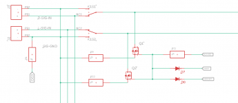
I've done a bit more work on this... this is my thought process so far:
1) I can't place a resistor from the non-inverting input to ground as it will be in parallel with the resistor on the output of the attenuator (R21&22).
2) I can't move the attenuator resistors (R21&22) after the switch as I want the option to have more than one output active and this will place those output resistors in parallel.
3) If I made the resistors very high in value to mitigate the impact on the attenuator, noise performance would suffer. If I'm wrong about this I'd be happy to be put right.
So I've botched together the solution shown... The idea is that the 12V relay supply holds the P channel Mosfet high then when the relays are operated the mosfets shunt the non-inverting inputs to ground. The relays are latching which means the mosfets will only be on for 100mS or so. The relays have two coils so there are two connections to the switched grounds via the D7 & D8.
I was thinking of using a Vishay TP0610K for the fet - really no idea of how to choose these, my main criteria are small footprint and a gate that will tolerate 12V.
Does this look like it would work?
Any advice (or better ideas) would be very much appreciated.
Attachments
Last edited:
A high value resistor will ensure that things which should be grounded (for DC) stay grounded even when the relay is between contacts. It won't hurt to have two or more of these in parallel, if it is a sufficiently high value. It won't contribute much noise because during normal operation it will be shunted by whatever is driving it.
Any switches in an audio path, whether source selection or volume controls, must have coupling capacitors and ground leak resistors to keep everything at 0V DC. Otherwise you will get clicks.
Any switches in an audio path, whether source selection or volume controls, must have coupling capacitors and ground leak resistors to keep everything at 0V DC. Otherwise you will get clicks.
I tried 1MΩ and the clicks were quieter but still too loud, I now have 115KΩ resistors in place and it's pretty quiet, the DRV135s are still popping a bit but the unbalanced output is good. I can live with it for now, I think I may end up moving the relays to the other side of the output buffers, which is what I probably should have done in the first place... it just seemed wasteful to have the op amps going when the outputs are off.
- Status
- This old topic is closed. If you want to reopen this topic, contact a moderator using the "Report Post" button.
- Home
- Source & Line
- Analog Line Level
- Preamp Output Pops & Clicks