Hi,
I've finally got around to boxing up and testing the preamp I started some time ago, discussed in this thread.
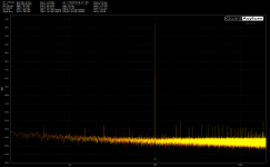
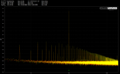
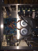
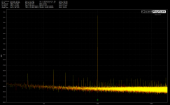
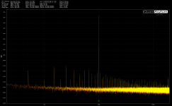
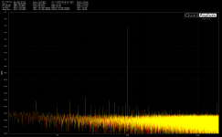
I've attached some images, one showing the loopback measurement of the Q401 I'm using and one with the preamp measurements. THD performance is better than I can measure but I've got a load of mains noise in there.
Each of the audio boards connected to DC ground locally via a 0R which I can swap out if needed. I'm thinking I need to try the following:
1) Moving the signal wires away from the trafos
2) Moving the trafos
3) Try some low value resistors in place of the 0Rs
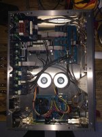
4) Try different locations for the chassis grounding (currently bottom left of the layout pic)
I guess what I'm asking is whether this sounds like a sensible plan and in the right order.
Any advice would be gratefully received.
Thanks,
Simon.
I've finally got around to boxing up and testing the preamp I started some time ago, discussed in this thread.
I've attached some images, one showing the loopback measurement of the Q401 I'm using and one with the preamp measurements. THD performance is better than I can measure but I've got a load of mains noise in there.
Each of the audio boards connected to DC ground locally via a 0R which I can swap out if needed. I'm thinking I need to try the following:
1) Moving the signal wires away from the trafos
2) Moving the trafos
3) Try some low value resistors in place of the 0Rs
4) Try different locations for the chassis grounding (currently bottom left of the layout pic)
I guess what I'm asking is whether this sounds like a sensible plan and in the right order.
Any advice would be gratefully received.
Thanks,
Simon.
Attachments
Yes, keep signal cables away from mains transformers.
Transformer wiring should be twisted.
Keep signal ground currents well away from the chassis - it may be that you are already doing this. There should be one and only one connection between the signal ground and the chassis. This should not be shared with any other connection e.g. a safety connection. Your chassis connection appears to have three wires to it. You should have two separate chassis connections, each with one wire.
Thanks for the advice, I'll twist up the transformer wires and re-route the signal wires.
Each of the boards has a separate DC and Signal ground layer which I connect with a 0R resistor, these return to the power supply board which is connected chassis and safety earth. I've got three connections to ground as there's a separate circuit for the logic and relay power. I'll move the combined audio DC and signal chassis terminal to a new location.
Each of the boards has a separate DC and Signal ground layer which I connect with a 0R resistor, these return to the power supply board which is connected chassis and safety earth. I've got three connections to ground as there's a separate circuit for the logic and relay power. I'll move the combined audio DC and signal chassis terminal to a new location.
I twisted the power wires and moved the signal cables as far away as I can from the trafo. The signal / audio power ground is now connected to a different chassis location. Looks like that saved around 4dB of noise.
Is there any reason not to stack the trafos? I could get the problem one right out of the way.
Is there any reason not to stack the trafos? I could get the problem one right out of the way.
Attachments
Ok, getting somewhere now after a lot of experimentation with the transformer positions. Here are the measurements and the best (measured) position for the transformers. Strangely its about 3dB quieter with them on their sides and face on to the audio circuits - not what I would have guessed - but overall about 12dB better than where I started.
Attachments
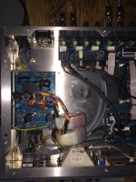
Strangely its about 3dB quieter with them on their sides and face on to the audio circuits.
Much of the noise radiates from where the leads enter the transformers,
so that area should be pointed away from sensitive circuitry.
The transformers are probably interacting with the audio circuit via magnetic fields. Magnetic fields couple to loops. You need to minimise the loop area, and get it as far away from the transformers as possible. If several stages in a box on separate PCBs are coupled by unbalanced shielded cables but also fed from one PSU it is quite possible that the loop area is not the tiny amount of a coax cable but also includes the ground connection back to the PSU. This ground wire will run near the transformers, so the transformers are near the loop.
I think that you may have hit on the problem... I have separate leads from the PSU to each of the boards (the grey wires are power) and signal connections between the boards (the black wires) - I'm starting to visualise a number of loops. Perhaps if I daisy chain the boards back to a single point on the PSU I can reduce the size of those loops. I'll knock up a cable this evening and see if that makes a difference.
I've not really got an idea of what good will look like in terms of measurement - should I be looking to remove all traces of ground noise from the frequency plot or is that an unreasonable expectation?
I've not really got an idea of what good will look like in terms of measurement - should I be looking to remove all traces of ground noise from the frequency plot or is that an unreasonable expectation?
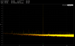
I made up a daisy chain supply with all boards sharing the same dc ground. I removed the averaging from the measurement to make the noise floor visible. Pretty much the same result as with the previous power cabling.
I'm wondering whether to try removing the 0R connection to dc ground from all the boards bar one to see if that makes a difference. The hum isn't audible but now I've started experimenting I'd like to see how low I can get it. I could try low value resistors instead of the 0Rs as well I guess.
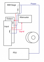
I've included a block diagram of the current layout. Any ideas?
I'm wondering whether to try removing the 0R connection to dc ground from all the boards bar one to see if that makes a difference. The hum isn't audible but now I've started experimenting I'd like to see how low I can get it. I could try low value resistors instead of the 0Rs as well I guess.
I've included a block diagram of the current layout. Any ideas?
Attachments
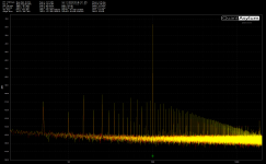
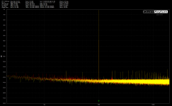
Got there in the end. I borrowed a couple of silicon steel bands from some other transformers I have and placed them around the transformers, the highest peak is now -110dB at 250Hz, the second image is the QA401 measurement in a loopback setup for reference.
Thanks for the help.
Thanks for the help.
Attachments

I hope this is not too much of topic, i was finishing f5 and m2 amps, and noticed slightly higher background noise with transformer in final position in the middle of the chasis. Someone suggested to rotate the toroidal transformer and observe the buz on ouput with scope. The difference was significant.
- Status
- This old topic is closed. If you want to reopen this topic, contact a moderator using the "Report Post" button.
- Home
- Source & Line
- Analog Line Level
- Preamp Tests