Hi! I'm trying to implement a DC servo, and here are 2 examples (Fig.1 is from a power amp. & Fig.2 is from Accuphase C-2810). Obviously, they are differ in RC values.
Q1. Most textbook examples prefer high value in R and low value in C (like Fig.1) . Doesn't high source resistor contribute much thermal noise into the circuit? Not to mention a Fet-input op amp was used here. (Fig.2 seems to be a better approach of this matter.) What's the disadvantage of increasing the C value (and lower R)?
Q2. How to choose a output resistor of a DC servo? (R22 in Fig.1 & R17 in Fig.2) What's the disadvantage of lowering its value? Let's say 100R or 1K?
Thanks.
Fig.1

Fig.2

Q1. Most textbook examples prefer high value in R and low value in C (like Fig.1) . Doesn't high source resistor contribute much thermal noise into the circuit? Not to mention a Fet-input op amp was used here. (Fig.2 seems to be a better approach of this matter.) What's the disadvantage of increasing the C value (and lower R)?
Q2. How to choose a output resistor of a DC servo? (R22 in Fig.1 & R17 in Fig.2) What's the disadvantage of lowering its value? Let's say 100R or 1K?
Thanks.
Fig.1
Fig.2
Last edited:
Servo
Ticknpop, wonder where you got the info on the Constellation Audio's servo resistor value at 30K?
I am looking at the Constellation schematics and I see 10K and 3K99 values.
Their servo circuits are in multiple stages and so do not use just one value
Their power amps do not use a servo for the actual power amp and only their Reference series uses a servo on the front end preamps.
Q1: high-valued capacitors are more expensive
Q2: small enough to regulate away the DC offset and small enough not to drive the op-amp into clipping when the input signal has a large subsonic or deep bass content. As long as those requirements are met, the smaller the resistor, the more impact the noise and distortion of the op-amp have.
Q2: small enough to regulate away the DC offset and small enough not to drive the op-amp into clipping when the input signal has a large subsonic or deep bass content. As long as those requirements are met, the smaller the resistor, the more impact the noise and distortion of the op-amp have.
Last edited:
For question 1, the choice of small C and large R is usually to use a physically smaller C, or in the case of surface mount, to be able to build the servo at all, since large C0G ceramic is not available. 0.1uF is generally the largest easily available C0G capacitor, so the resistors will be scaled to that. Yes, using a larger R will cause higher noise, but keep in mind that this noise is lowpassed by the integrator, so it's not as important as one would imagine. Still, noise will be larger, according to the input current noise of the servo amp.
Another effect of a larger integrator R is to increase the DC offset because of input bias current effects. Servo amp input bias currents will interact with the input R create an input voltage error that adds to the input voltage offset of the servo amp, and this is part of the final DC error of the servo circuit as a whole. With "auto-zero" op amps, e.g. chopper amps, even though they may use a FET input stage, their switching artifacts can look like additional input bias current when lowpassed by the input RC network, and this will act with the larger R to increase the total DC error of the servo.
Traditionally, people don’t seem to worry about the residual offset of the servo amplifier, but I’m not sure why, given the excellent amplifiers available now. With an Analog ADA4522 amplifier, it’s not difficult to get a very low noise, low distortion servo with an ‘end of the day’ offset of around 5-7µV, far better than the 2-3mV from the typical ancient BiFET op amps used as integrators.
For question 2, the choice of the servo output resistor is critical in order to tune the frequency response (or settling time) of the servo circuit as a whole.
The servo integrator time constant affects the overall highpass frequency, but the actual net highpass frequency also depends upon the loop gain of the servo and the controlled amplifier stage. Included in this loop gain is the gain from the servo amplifier through the servo output resistor into the ‘force’ node. That attenuation is part of the overall loop gain, and it determines the dynamics of the servo.
Fortunately, it is generally helpful to have this attenuation from the servo amplifier into the servo controlled circuit. Since a larger output resistor decreases the overall servo loop gain, it will also reduce the corner frequency of the servo. This allows a smaller integrator capacitor and/or resistor, which is generally preferable. The attenuation from a larger output resistor will also attenuate the noise of the servo amp itself.
The tradeoff of attenuating the servo output is that the DC correction range of the servo will be reduced, since the servo amp's output is attenuated. In other words, a servo amplifier that can swing ±12V driving a 10:1 attenuator will only be able to correct a ±1.2V offset. However, the corner frequency of the servo as a whole is now reduced by a factor of 10, and the noise of the servo amp as a whole will be reduced by 20dB. A larger servo 'force' resistor is also less invasive to the controlled circuit - it will not load down the servo's force node as greatly as a smaller force resistor, making it easier to use the servo.
I find it's easiest to use something like LTspice to tune a DC servo, since it will take the entire amplifier gain and all of the related source and load impedances into account. This makes it easier to poke at the circuit and come up with a reasonable tuning. I find that an overall highpass frequency of the servo around 1-3Hz is a good ballpark target, and by using an AC simulation to examine the net frequency response, component value choices are easier to optimize. LTspice is also useful to estimate the net output DC offset, as long as all of the amplifier models provide accurate input offset current and voltage values.

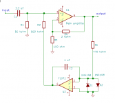
There are other ways to make a servo, such as this one. If dimensioned properly it can have a nice second-order response and it doesn't require much performance from the op-amp; the op-amp's noise is attenuated well and there is only little audio signal current flowing through the op-amp's output.
Attachments
With an Analog ADA4522 amplifier, it’s not difficult to get a very low noise, low distortion servo with an ‘end of the day’ offset of around 5-7µV, far better than the 2-3mV from the typical ancient BiFET op amps used as integrators.
hi Monte McGuire,
Thanks for the detail explanation. I currently using ADA4522 as the servo. I am trying to lower the 1/f noise as well as thermal noise here. Before ADA4522, a AD8671 was used, but it has higher Ib. ADA4522 seems to be the optimal op amp so far. Speaking of the servo output resistor, I found it has strong impact on the sound. With lower value (e.g. 500R), the HF is brighter and deep bass is reduced. I finally settled with 1.3k where I think is the sweet spot for me.
Since I'm implementing an inverting servo with only 3.3K input resistor, I'd probably add a buffer before it. So, an ADA4522-2 is on its way...
Poting
Last edited:
There are other ways to make a servo, such as this one. If dimensioned properly it can have a nice second-order response and it doesn't require much performance from the op-amp; the op-amp's noise is attenuated well and there is only little audio signal current flowing through the op-amp's output.
hi MarcelvdG,
Thank you for the schematics. It's pretty much like my early implementation. I'm sure it will work flawlessly. However, I am trying to lower the noise as possible as I can, the TL071 seems not the best candidate here, albeit with J-Fet input. With the tweaked version, I found the bass was more clearly defined. I suspect this could be the effect of lowering the combined noise of a servo.
Poting
- Status
- This old topic is closed. If you want to reopen this topic, contact a moderator using the "Report Post" button.
- Home
- Source & Line
- Analog Line Level
- Questions about DC servo