Hi
I have an APT preamp which has a problem on one channel when I measure the noise and distortion. I have worked on a bunch of these and they reward, in my humble view, improving the components.
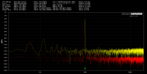
So the problem is illustrated in the attached plot from my QA401- the right channel measure as it should but the left has a hefty 120hz hum and thus higher distortion and worse SN figures.
I started looking for the obvious and connected the QA to the external processor outs to determine where in the circuit the problem is occuring- up to these outputs all is well and measures as it should. So then I started measuring the volume, mode and balance section IC's as the tone controls are switched out. IC's 6,7 and 8 all measure 0v on their inputs and outputs, however IC5 measures 7.72v on the right output (pin 7) and 0.334v on the left output (pin1) - both left and right inputs (pins 2,3,5,6) all measure 14.12v.
I have checked the surrounding components for obvious failures and replaced Q12 and Q13 and IC5 all to no avail.
The manual states that the wiper of the volume control should be 0v, whereas all three connectors on the volume pot are the same as the outputs of IC5.
As I am not that familiar with this interesting volume design approach any thoughts are greatly appreciated.
Peter
I have an APT preamp which has a problem on one channel when I measure the noise and distortion. I have worked on a bunch of these and they reward, in my humble view, improving the components.
So the problem is illustrated in the attached plot from my QA401- the right channel measure as it should but the left has a hefty 120hz hum and thus higher distortion and worse SN figures.
I started looking for the obvious and connected the QA to the external processor outs to determine where in the circuit the problem is occuring- up to these outputs all is well and measures as it should. So then I started measuring the volume, mode and balance section IC's as the tone controls are switched out. IC's 6,7 and 8 all measure 0v on their inputs and outputs, however IC5 measures 7.72v on the right output (pin 7) and 0.334v on the left output (pin1) - both left and right inputs (pins 2,3,5,6) all measure 14.12v.
I have checked the surrounding components for obvious failures and replaced Q12 and Q13 and IC5 all to no avail.
The manual states that the wiper of the volume control should be 0v, whereas all three connectors on the volume pot are the same as the outputs of IC5.
As I am not that familiar with this interesting volume design approach any thoughts are greatly appreciated.
Peter
Attachments
So many things wrong here, I do not know where to start.
IC5 should have one pin at +15V, one at -15V, and all the rest very close to zero. Under 0.1V. You should see this pattern on all the opamps in this plan.
You say the bad channel is 0.3V, and the good channel is 7V??
Emitter of Q10 should be a few Volts negative; are you really seeing a positive voltage here?
I should have clarified- all the VCC+ and VCC on IC5(and the other IC's-6,7,8)-pins 4 and 8 are at +15 and -15 yes the voltage measurements are what have me-, I do not understand why pins 2 and 3- inputs for the right channel and pins 5 and 6 inputs for the left channel are all at 14v. nor would I expect 7.7v on the "good" channel. Changing the volume level makes no difference as well I measured Q10 emitter and it at -0.35v thanks
Because an opamp has very high gain of about 100,000. So you only need a difference of 70uV between pins 2 and 3 to get 7V on pin 1, you won't be able to see that on a normal meter. Note the word 'difference' - it doesn't matter that both pins are at 14V, it's only the difference betwwen input pins that an opamp responds to.... I do not understand why pins 2 and 3- inputs for the right channel and pins 5 and 6 inputs for the left channel are all at 14v. nor would I expect 7.7v on the "good" channel.
But your diagram says +1.1V at that point, anyway it's the right channel thatChanging the volume level makes no difference as well I measured Q10 emitter and it at -0.35v thanks
clearly has a fault because +7V out of U5 is not possible when everything is working properly.
By way of some explanation:
Q12+Q13+U5A together make an extended opamp. Q12 base is the inverting (-ve) input, Q13 base is the non-inverting (+ve) input. U5 pin 1 is the output of course.
Now Q13 base (+ve in) is connected to GND and Q12 base (-ve in) is connected to U5 pin 1 (out) through R41 and R42. There is no other DC connection path to the -ve input. So for DC, this extended opamp is just a unity gain buffer of whatever is on the +ve input, which is GND. So U5 pin 1 must also be at GND.
For AC, this opamp works as a normal inverting opamp circuit whose variable gain is largely set by the two sections of the volume control either side of the wiper, that's how a Baxandall volume control works.
You have a fault in the right channel somewhere. Double check all power rail connections, not just the opamp power pins but all the other components that connect to the power rails, like top end of R43 & R46, bottom end of R48, etc. Also Q13 base! Try to get the meter probe on the component lead, not just the track/pad it's supposed to be soldered to, otherwise you can miss a bad solder joint. Then you can check for sensible voltages around transistors voltage drop across resistors, etc.
As said by EssB, the transistors and chip make a composite opamp, which obeys all the usual rules. I have hacked the schematic (below) to show the op-amp, and its feedback. Since you have DC trouble, ideally the caps are not in the DC picture, so I trimmed them.
All that's left is an opamp with its negative input (Q13 Base) at ground, and its positive input connected to output via a negligible 101K resistance. A simple Voltage Follower.
If the problem is not found that way, document all the voltages around Q12 Q13. I have penciled some guesses.
All that's left is an opamp with its negative input (Q13 Base) at ground, and its positive input connected to output via a negligible 101K resistance. A simple Voltage Follower.
If the problem is not found that way, document all the voltages around Q12 Q13. I have penciled some guesses.
Attachments
Sounds like reft and light channels have been accidentally misidentified tbh. (Can't hurt to check the unit input to output just in case, accidental swaps do happen once in a while.) Pretty sure the one with the +7.72 V on it has a problem. Check for opens on the Q5 - R42 - R41 - Q12 route - maybe a bad resistor, solder joint or trace.
Thank you all so much for your explanations- I think I am beginning to understand how this section operates. @sgrossklass- I will double check the right/left channels ( I am a tad dyslexic- so i regularly get right and left confused) @PRR- thanks for the diagram - that really helps me understand what should be happening @EssB- thanks for the explanation- that has really helped me understanding the theory and intention I have a couple of days where I have to get some other day job work done, so will get to this on friday and report back. Again thank you so much for you input Best regards to all Peter
HI all
I have attached the circuit with all the voltages for both channels.
@sgrossklass- The continuity between base of Q12 and pin1 of IC5 is 102k, as expected- I have replaced both R41 and R42- (the original fitted R41 was 220ohm- not 1k- which I suspect has been this way since new-and would not make much difference anyhow)
I have also replaced the fitted 2sc1845 for Q12 and Q13 and Q112 and Q113 with Ksc1845 and matched their HFe
When I measure the voltages on Q10/Q11 and Q111 and Q110- base and emitter for both- there is a larger current draw by the preamp- meter is a battery powered Fluke
I have resoldered the connections in the volume section and checked the continuity of the traces- all seems as it should...and spent considerable time staring at the pcb with a magnifying glass- all to no avail.
sorry about the delay in getting these figures back to you- I greatly appreciate your assistance
Best Regards
Peter
Attachments
any insights very much appreciated.
Have you replaced C35?
yes on both channels with Nichicon KZ
Since the stage is DC isolated by C35, about all that could be wrong is a bad solder joint,
or else a bad part, like Q12, Q13, or IC5A.
I have replaced Q12, Q13 and IC5- so I will re-solder all the joints in that section
Check the resistors too, while you are at it. There are only a few parts.
I Think I will remove all the components and make sure the track connections
are good and then reinstall once I have tested them
I would avoid work on the pcb unless necessary, as it could easily be damaged.
You can verify the trace continuity in circuit just as well.
- Status
- This old topic is closed. If you want to reopen this topic, contact a moderator using the "Report Post" button.
- Home
- Source & Line
- Analog Line Level
- APT preamp left channel noises