Hello,
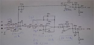
I am a beginner at building circuits. I have got a drawing from a professional, that should be a correct circuit for crossing audio to a top speaker and a subwoofer.
I am bit confused about how to connect ground. Should I just connect all the points that is marked as ground, and that's it?
I am also now sure about connecting the potentio meters. As I searched, it seems to me, that I should pin 1 to ground, pin 2 is input and 3 is out, is it correct?
At the current stage, if I connect my phone's headphone output to the input and a speaker to the output, I experience a strange anomaly '")
The output volume starts rising, and when it reaches a certain level, it mutes and the process starts over again... at max point, the output volume is still much lower than the original level from the phone's output. It is also clipping above like 60% of phone volume.... If I adjust the potentio meter, they do something, but with these circumstances I cannot determine if it changes the crossover frequency, volume, or what...
Can someone help, please?
I am a beginner at building circuits. I have got a drawing from a professional, that should be a correct circuit for crossing audio to a top speaker and a subwoofer.
I am bit confused about how to connect ground. Should I just connect all the points that is marked as ground, and that's it?
I am also now sure about connecting the potentio meters. As I searched, it seems to me, that I should pin 1 to ground, pin 2 is input and 3 is out, is it correct?
At the current stage, if I connect my phone's headphone output to the input and a speaker to the output, I experience a strange anomaly '
The output volume starts rising, and when it reaches a certain level, it mutes and the process starts over again... at max point, the output volume is still much lower than the original level from the phone's output. It is also clipping above like 60% of phone volume.... If I adjust the potentio meter, they do something, but with these circumstances I cannot determine if it changes the crossover frequency, volume, or what...
Can someone help, please?
Add .1uF decoupling caps on the opamp PS leads to prevent opamp instability. If the opamps are oscillating, could be the cause of your volume symptom.
It might be difficult to read the schematic, so make sure you used all the right part values. 4k7 means 4.7kOhms. 1uF, 220uF, 470uF caps. 100 Ohm, 100kOhm, 2.2kOhm resistors, etc.
Download the datasheet for the pots to see how they should be wired.
There's more to good grounding than just connect them all together, but you could start there.
That's true.Hi, I haven’t looked at this in detail, but just at first glance, the sub channel doesn’t work. When looking at op amp circuits, the first thing I look for is a dc path for input bias for each input. The middle op amp has no bias path for the positive input.
But is there any reason why you wouldn't try the Linkwitz-Riley crossover?
Linkwitz-Riley Electronic Crossover
- Status
- This old topic is closed. If you want to reopen this topic, contact a moderator using the "Report Post" button.