Since I think I am finalizing the design I am posting the updated schematics and BOM. Once I build up the new PCBs and re-test the design and listen to it then I will post the Gerbers.
Attachments
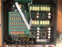
My new circuit boards arrived a day early on Thursday and that evening I started stripping parts off the old boards and soldering them into the new boards. Finished on Friday and started testing, the EEPROM code for the three digit volume display worked perfectly. The rotary encoder is set to step 4x but if you push in on the knob you can single step, so go up fast then you can fine tune the volume. I tried the PEC12R version of the encode with soft detents on the first board and that felt good. On this version I used a PEC11R encoder which has a higher detent force and I didn't care for the feel. On the third, and hopefully final version, board I will try a rotary encoder with no detents like the Pass Aleph P which feels smooth.
I had one problem with the set of boards, the mute circuit kept triggering with movement of the rotary encoder. Traced it to noise on the signal lines. The mute button controls are on the display board with goes over to the Flip Flop on the digital board whos output signal goes back to the display board to light the mute LED and also goes to Analog board to pull in the mute relay. I figured if I moved the Flip Flop chip to the display board I could eliminate the back and forth of the signal, isolating the circuit all in one area. To test the idea I pulled the flip flop chip from the digital board, made on trace cut on the display board and added the flip flop chip to the display board dead bug style (upside down and legs splayed out). The circuit now functional without error, no false triggering.
I will update the schematics and turn new display and digital board gerbers and order a few more parts. In a couple weeks the finally design should be ready to test.
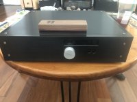
On another note, the CAD files for the chassis that I sent to a machine shop in China arrived Wednesday, they produced some very good quality parts for the preamp chassis. With 1/2" thick faceplate and side panels and 1/4" thick top, bottom, and back panel this will be a substantial feeling preamp. With a fine brushed finish and black hard anodizing the parts are beautiful. Once assembled I will weigh it and post pics. The parts cost me half of what a USA machine shop that I usually use quoted me, even with shipping heavy packages express from China. I highly recommend the shop. You can check them out online at Runson.com.
I had one problem with the set of boards, the mute circuit kept triggering with movement of the rotary encoder. Traced it to noise on the signal lines. The mute button controls are on the display board with goes over to the Flip Flop on the digital board whos output signal goes back to the display board to light the mute LED and also goes to Analog board to pull in the mute relay. I figured if I moved the Flip Flop chip to the display board I could eliminate the back and forth of the signal, isolating the circuit all in one area. To test the idea I pulled the flip flop chip from the digital board, made on trace cut on the display board and added the flip flop chip to the display board dead bug style (upside down and legs splayed out). The circuit now functional without error, no false triggering.
I will update the schematics and turn new display and digital board gerbers and order a few more parts. In a couple weeks the finally design should be ready to test.
On another note, the CAD files for the chassis that I sent to a machine shop in China arrived Wednesday, they produced some very good quality parts for the preamp chassis. With 1/2" thick faceplate and side panels and 1/4" thick top, bottom, and back panel this will be a substantial feeling preamp. With a fine brushed finish and black hard anodizing the parts are beautiful. Once assembled I will weigh it and post pics. The parts cost me half of what a USA machine shop that I usually use quoted me, even with shipping heavy packages express from China. I highly recommend the shop. You can check them out online at Runson.com.
Last edited:
Yes I am going to have to make one more turn of the digital and display PCBs. It is a bit wasteful having to toss 9 PCBs of each that do not function perfectly not to mention a $100 a turn for the two sets of boards. Oh well, I want these functionally and sound wise to be the best I can produce.
The Display board does require one chip to be programmed. For anyone that buys a set of boards I will supply a programmed EEPROM, I will even solder it onto the board, a 28 pin SOIC chip. Thinking about it the Quadrature decode chip for the rotary encoder isn't easy to get outside the US so could include one of those also.
The Display board does require one chip to be programmed. For anyone that buys a set of boards I will supply a programmed EEPROM, I will even solder it onto the board, a 28 pin SOIC chip. Thinking about it the Quadrature decode chip for the rotary encoder isn't easy to get outside the US so could include one of those also.
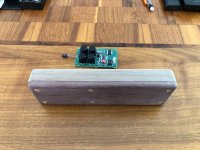
For the remote, as well as other boards, I will have to supply the hole dimensions so people can create enclosures. I can also post a pic of a commercial enclosure for the remote and one I started with just plate aluminum and bar. I had one friend who is a wood worker and made one from Walnut, was beautiful.
I have a CAD drawing for the faceplate of the preamp enclosure that I can supply. Still need to take pics and post.
I have a CAD drawing for the faceplate of the preamp enclosure that I can supply. Still need to take pics and post.
A couple days ago I ordered a new set of the digital and display boards. Today I ordered a few more parts to populate them. I discovered that the blue 7-segment LED display, Common Cathode, has been discontinued, this is the through-hole version, the surface mount version is still available. I will have to update the display board layout again to use the surface mount ones as people prefer blue, the red and green through-hole displays are still available.
I have looked at the layout of the Display board and I might be able to create a part pattern that has both through-hole and surface mount for the Seven segment display parts so no matter which are available either will fit and work. Unfortunately the 10 boards I just ordered won't have that feature, the leds will have to be through-hole.
My order of parts came in from Mouser and the ribbon connector headers were the wrong size, I wanted 8 position by 2 rows and the spec has 8 position as 4x2 so I updated the BOM part numbers and ordered some correct connectors along with a few surface mount seven segment LED displays to check fit on the board layout once I get the new part pattern created. The new run of PCBs should be here next Wednesday as will the parts so will be ready to build the final boards, at least I hope it is the final round. ")
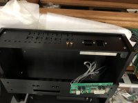
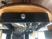
And some pics of the preamps I am building, one with the old design volume board with the updated resistor values, and one ready for the new volume boards when ready. These chassis I had machined based on the Pass Aleph P are heavy duty. The preamp section is based on the Aleph P which I own so I have a constant for comparison.
Attachments
So I did an informal poll of some friends about the display: is it better to display the number 80 as 080 on the display or just show 80, 001 as just 1. That is called leading zero suppression. All of them voted for leading zero suppression, so I have updated the EEPROM data file, then tested it. I will post the new file soon.
I received the new PCBs yesterday as well as the Mouser parts drop so I am ready to build the last, hopefully, version of the volume control.
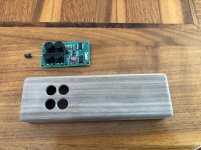
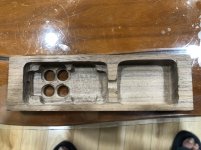
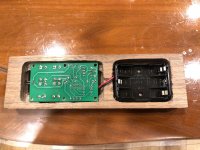
But in the mean time I have been working on a Walnut case for the remote which will be a nice touch. I will post pics of it when done.
I did finish building the first preamp with the original volume control board, with the updated resistor value which doesn't load the input sources too much, and the Aleph P preamp section. I was so impressed with everything about the sound, bass extension, extended smooth highs, pin point focus and natural timber, that I played music disk after disk for three hours. Nelson Pass design of Zen, fewer parts and simple circuits really works. I have the Pass Labs Aleph P preamp but I used a few different parts in my build and it actually sounds better, I was just amazed. I was even more amazed that it started up and worked properly first time.
I received the new PCBs yesterday as well as the Mouser parts drop so I am ready to build the last, hopefully, version of the volume control.
But in the mean time I have been working on a Walnut case for the remote which will be a nice touch. I will post pics of it when done.
I did finish building the first preamp with the original volume control board, with the updated resistor value which doesn't load the input sources too much, and the Aleph P preamp section. I was so impressed with everything about the sound, bass extension, extended smooth highs, pin point focus and natural timber, that I played music disk after disk for three hours. Nelson Pass design of Zen, fewer parts and simple circuits really works. I have the Pass Labs Aleph P preamp but I used a few different parts in my build and it actually sounds better, I was just amazed. I was even more amazed that it started up and worked properly first time.
Tonight I finished stripping the parts off the old PCBs and putting them on the new boards. And it worked, after I discovered that I have the ribbon cables reversed. I used the rotary encoder with no detents this time and find I prefer it. Now I can build up the second preamp and see if it sounds as good as the first one.
I am trying to attach pics of the walnut case for the remote but the system is giving me problems. Will try again soon.
I am trying to attach pics of the walnut case for the remote but the system is giving me problems. Will try again soon.
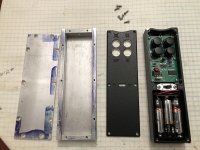
Here is a couple pics of the remote.
Attachments
-
 A4551A21-0522-4435-832C-16F3CE46F592.jpg990.4 KB · Views: 292
 -
 F262C3B7-FA4D-4406-BA67-39D2839BF3CB.jpg1,012.5 KB · Views: 280
 -
 CE1CAA2E-4E74-4C8F-8411-70CB92A490B9.jpg1,018.7 KB · Views: 158
 -
 007D3899-301F-47ED-8C4B-F9FD1221C81B.jpg990.7 KB · Views: 168
 -
 D0CDDAFC-CD7F-47C9-AF80-909E7F115568.jpg956.5 KB · Views: 134
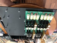
Today I finished putting together my new preamp using the new volume control board and I have been listening to it all evening. It sounds pretty good, with good source material it is as transparent as I have heard. In a couple days I will take it to my audio business friend and let him listen to it for a couple weeks to get his opinion then I can release the new BOM and gerbers. It is an easy and straight forward build but I will write a quick build guide for it as well. I will take some pics of the boards in the preamp and preamp itself.
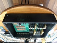
And here is a couple pics of the preamp. Unfortunately when I made the display board larger I moved the mounting holes and enlarged the pocket in the front to hold it but forgot to move the push button holes down. I will fix the CAD file before posting it.
Attachments
Attaching updated BOM and gerbers.
Next will be CAD files for the Chassis and Build instructions for the PCBs and connections.
Next will be CAD files for the Chassis and Build instructions for the PCBs and connections.
Attachments
ok, did the schematic to pdf thing.
Attachments
- Home
- Source & Line
- Analog Line Level
- Preamp Control - Volume, input, mute, remote