So, I thought about starting a new thread for this now design but what the heck.
Here is the schematic of the new ladder typology volume controller. It has a separate power supply board, a Digital control board which takes input from the display board which has a rotary encoder for volume and push buttons for mute and input select. The rotary encoder will fine step the volume if rotated but push in to activate fast stepping mode, 4x. The analog board stacks on top of the digital board to save space. The remote is the same as before.
See how the schematics look to you and if you find any problem be sure to let me know.")
So I will turn some boards, build them up and test the design soon. After I am sure it works properly and sounds good I will post the gerbers.
Here is the schematic of the new ladder typology volume controller. It has a separate power supply board, a Digital control board which takes input from the display board which has a rotary encoder for volume and push buttons for mute and input select. The rotary encoder will fine step the volume if rotated but push in to activate fast stepping mode, 4x. The analog board stacks on top of the digital board to save space. The remote is the same as before.
See how the schematics look to you and if you find any problem be sure to let me know.
So I will turn some boards, build them up and test the design soon. After I am sure it works properly and sounds good I will post the gerbers.
Attachments
Last edited:
John
I am interested in your design, I built a Wayne’s 2018 line stage and used a off the shelf volume control and selector from eBay and it is a disappointment. Since I purchased XRK Yarra boards and would like to add a nice controller. If you don’t offer any boards maybe I will get some made and offer the extras in the group buy section if it’s ok with you. I am still moving into a new house myself so my hands are still full with house projects ahead of the Yarra but I am retired and don’t mind planning ahead.
Bill
I may have a couple boards left when I am through testing.
Found a problem with the Analog board already, it was missing the input load resistors. attached is the updated schematic.
Here is the BOM for the boards. It is a costed BOM, nice to know what the project will cost. To do that you have to sort through parts and quantities, what's in stock, etc. Took almost a full day to do it, a bit of a pain but worth the effort to double check the design.
This project is a little more expensive as it take twice as many quality resistors, and the cost of semiconductors has gone up a bit with the shortage of silicon wafers.
Attachments
Last edited:
Last night I turned gerbers for the 4 boards and sent in the order and the PCBs are in production now. I placed a parts order with Mouser for everything but the quadrature encoder which I got from US Digital.
After I build and test the design I will post gerbers.
Also, as you can see from the Analog board schematic this is a 6 input balance design. It can be used Single Ended (SE) by stuffing one side of the board but to save space I will also create a Single ended Analogue board for those that only want Single Ended. And I guess I need to highlight the BOM to show what to buy for SE.
Last edited:
The new PCBs arrived on Friday and I proceeded to build up one of each. While making the Bill of Material helps find issues with the schematic building the boards helps find problems with the BOM. Attached is the updated BOM. Turns out I left off two resistors, one chip, and the end connectors for the ribbon cable. So another order of parts from Mouser has been placed. I tested the Power Supply board which works but have to wait on the parts to complete and test the other boards. And if there is room on the PCB I am going to make some of the resistors larger so a wider range of types can be used. Some resistors are 3.4 mm long and fit easily but not always available so will update the PCB layouts.
Attachments
Over the past week I have been debugging the new parts of the design and figured out a problem with the rotary encoder. I will have to update the schematic and then change the PCB. The output of the decoder needed to be inverted Before the OR gate to feed the counter chip so I used a few of the spare Hex Inverter gates. One last problem with a flicker in the display needs an adjustment to the one-shot. This is the second time this issue has popped up. I am seriously thinking of removing all the parts that feed the display and replace it with a multiplexed EEPROM. See UTube, Ben Eater on displaying 8 bits on a 3 digit display. But an EEPROM would need to be programmed changing my first requirement of not requiring any programming of chips. If I can find an easy way to program a 8k x 8 EEPROM, which are inexpensive, then I will continue down that road.
For now I will finish this design. The digital control may change but the analog section will remain the same. I am excited to listen to the ladder type resistor attenuator and see how it compares with the the digitally weighted resistor attenuator.
For now I will finish this design. The digital control may change but the analog section will remain the same. I am excited to listen to the ladder type resistor attenuator and see how it compares with the the digitally weighted resistor attenuator.
After a week of trying various tweaks I still have a flicker in the display digits at 16, 32, 64, etc. Without a logic analyzer which is way to expensive for me or some really good sim software I can't figure the timing issue, the design has three different signals that need to occur in the proper order and pulse width. So I am going to work on the EEPROM decoding for the display which will have no timing to worry about. At least I can do some listening tests with the controller with a flaky display while I find a good programming environment for the EEPROM. I have already written the program to generate the data file for the display.
The flickering display is the only issue remaining. The rotary encoder works well, if I had looked at the output diagram of the decoder data sheet a little closer I would have put the inverters in the signal path to start with. So the current design is functional except for the occasional display flicker.
Attached is the schematics for the Version 2 of the design using a EEPROMs data to light the LED segments. I think I have found an inexpensive USB driven PROM programmer.
I haven't had time to do any listening to it yet but will soon and give the measured input impedance.
Attached is the schematics for the Version 2 of the design using a EEPROMs data to light the LED segments. I think I have found an inexpensive USB driven PROM programmer.
I haven't had time to do any listening to it yet but will soon and give the measured input impedance.
Attachments
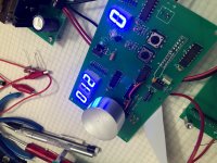
And here is a couple Pics of the boards. The rotary encoder is under the home made knob. I used 32mm aluminum round stock and cut off about 18mm long, drilled, sand, clear coated. $1 knob instead of $15.
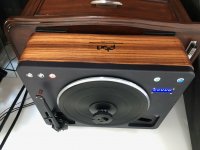
And just for fun I have included a pic of the turntable my audio business friend helped my build using my zebra wood, Denon DP80 table, SME V tonearm and Koetsu Rosewood Signature cartridge.
And just for fun I have included a pic of the turntable my audio business friend helped my build using my zebra wood, Denon DP80 table, SME V tonearm and Koetsu Rosewood Signature cartridge.
Attachments
I finally found some time to add input and output connectors to the board and cabled the output of the preamp to the volume control board input and its output to the amps. With the preamp set to max volume I could control the volume with either the rotary encoder knob or the infrared remote. Where the digitally weight volume was mostly useful in the bottom 30% for most inputs the resistor ladder board is quiet until you reach about 60% of the range since the steps are small. I started listening to it and something sounded a little off. I tracked it down to a stupid mistake of crossing the positive and negative leads at the output putting the left channel out of phase. A few seconds with the soldering iron fixed it but I will need to correct the schematic and board layout, a small change. But I have been listening to it all evening and enjoying a lot of music. It is very transparent, I can hear poorly recorded tracks but quality recording sound awesome. I have a Sheffield Labs demo disk with a saxophone recording that blew me away, literally; sounded like he was in the room playing for me.
Working on the PROM programming for the display, once done I will have some more boards made and build up another set to test.
Working on the PROM programming for the display, once done I will have some more boards made and build up another set to test.
Last edited:
The boards in the earlier threads used a digitally weighted scheme to parallel in volume control resistors. The input resistance changed with each resistor added. With the original resistor values the input dropped to 160 ohms which most sources had trouble driving resulting in increased distortion or at least compressed sounding dynamics. With the updated values it dropped to 330 ohms which my components can drive but not everyones. So I am trying the ladder resistor scheme, at least that is what most sources I looked at called it. The new scheme can be setup with either a fixed input or output resistance. For this project I choose a fixed input resistance of 10k.
The new scheme requires twice as many resistors as the previous so it is very important to use quality resistors. I saw the test of many resistors in an early Linear Audio issue, thank Jan for that great magazine, and choose the Vishay/Dale RN65 or RN70 resistor series. Sound wise I can find no fault in the new resistor scheme after a long evening of listening to a wide variety of material.
I will post updated schematics soon and get some updated PCBs made and do further listening.
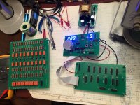
As you can see in the photo there are four boards, a power supply, display, digital, and analog. There are two versions of the analog board, the larger one is for two channels of balanced signal and a smaller board, essentially half of the balanced board, where the positive signal is used for left channel and the negative signal is used for right channel in a single ended system. I guess you could use the balanced analog board for a 4 channel single ended system if you wanted to.
The picture shows the analog board just set aside while I was using the oscilloscope and multimeter to kill a bug in the design, in actual use it stacks over the digital board using 3/4" standoffs saving a small amount of space inside the preamp chassis. I will post a picture of the boards together under listening test conditions.
The picture shows the analog board just set aside while I was using the oscilloscope and multimeter to kill a bug in the design, in actual use it stacks over the digital board using 3/4" standoffs saving a small amount of space inside the preamp chassis. I will post a picture of the boards together under listening test conditions.
Picked up one of the XGecu TL866 II+ Universal Programmers from EBay with enough adapters to do a DIP and a SOIC version of a 8k x 8 EEPROM. Then I wrote a C program to created the data file for the first 1k of the EEPROM, actually only need 768 locations for this project. I had to transpose the data bytes by putting in an ascii value which the C program writes as a decimal equivalent which the prom programmer converts to hexadecimal. Once I figured out the first 10 bytes the rest is just a repetition. I will post the C file and the .txt data file once I finish testing so anyone can use it. Or I can supply programmed chips, They are only $5 from mouser.
Last night I finished debugging and tonight I created gerbers and ordered a new set of boards for the Display and Digital board. The power supply and analog board didn't need any changes. When the new boards get here, probably within two weeks, I will build up a set and re-test. I will have 9 complete sets of boards left when done if anyone is interested.
Hi Samoloko, I will save 1 set of PCBs for you. I am not going to make any single ended boards but will provide gerbers for anyone who wants it.
Here is the Data file for the EEPROM. It say it is a .bin file which works for the PROM programmer but it is really a text file.
Here is the Data file for the EEPROM. It say it is a .bin file which works for the PROM programmer but it is really a text file.
Attachments
- Home
- Source & Line
- Analog Line Level
- Preamp Control - Volume, input, mute, remote