Ok, here is the corrected code for the input selection, Since the one pin starts low it probably wouldn't have been an issue since it is just in setup.
/**********************************************************************************
This program controls the functions of relays on a PCBs to set Input Selection,
The controller is a Arduino Nano and the pins relate to the processor named pins
not the pin numbers of a 30 pin DIP device.
***********************************************************************************/
// Global variables
// Input Relay control output pin variables
const int Relay1=6, Relay2=7, Relay3=8, Relay4=9;
// LED control output pins variables
const int LED1=2, LED2=3, LED3=4, LED4=5;
// Volume Encoder D14/A0 and D15/A1
const int EncoderAPin=A0, EncoderBPin=A1;
// variables have to be volatile for use in the Interrupt Service Routine and in the Main Loop
volatile byte seqA = 0;
volatile byte seqB = 0;
volatile boolean InputUpInt = false;
volatile boolean InputDownInt = false;
int input=1;
// the setup function runs once when you press reset or power the board
void setup() {
//set input and LED pins to outputs to control relays
pinMode(LED1, OUTPUT); //pin D3 (see variable names above)
pinMode(LED2, OUTPUT); //pin D4
pinMode(LED3, OUTPUT); //pin D5
pinMode(LED4, OUTPUT); //pin D6
pinMode(Relay1, OUTPUT); //pin D7
pinMode(Relay2, OUTPUT); //pin D8
pinMode(Relay3, OUTPUT); //pin D9
pinMode(Relay4, OUTPUT); //pin D10
//set volume Encoder, input, and mute button pins to input
pinMode(EncoderAPin, INPUT); //pin D14
pinMode(EncoderBPin, INPUT); //pin D15
//set output pins for volume and mute to off, and input select relay to input 1
//Volume is in binary converted from Decimal, The input relay control is BCD
digitalWrite(LED1, HIGH);
digitalWrite(LED2, LOW);
digitalWrite(LED3, LOW);
digitalWrite(LED4, LOW);
digitalWrite(Relay1, HIGH);
digitalWrite(Relay2, LOW);
digitalWrite(Relay3, LOW);
digitalWrite(Relay4, LOW);
PCICR = 0b00000010; //PCIE1: pin Change interrupt Enable 1
PCMSK1 = 0b00000011; //Enable PIN Change Interrupt for A0 and A1
} //End of Setup
// Interrupt Service Routine
// Every detent in the rotary encoder generates 4 pin changes, 2 on Pin A and 2 on Pin B
ISR (PCINT1_vect){
//When Interrupt triggered read encoder pins
boolean A_val = digitalRead(EncoderAPin);
boolean B_val = digitalRead(EncoderBPin);
//Record Pin A and B sequences in the global variables
seqA <<= 1; //shift the current byte date over one bit to the left
seqA |= A_val; //OR in, add, the new bit value, 0 or 1, of the encoder pin A
seqB <<= 1; //shift the current byte date over one bit to the left
seqB |= B_val; //OR in, add, the new bit value, 0 or 1, of the encoder pin A
//Mask the Most Significant four bits
seqA &= 0b00001111; // wipes off the previous four reads that were moved
seqB &= 0b00001111; // to the four higher bits
//Compare the recorded sequence with the expected sequence
if (seqA == 0b00000011 && seqB == 0b00001001){
InputUpInt = true;
}
if (seqA == 0b00001001 && seqB == 0b00000011){
InputDownInt = true;
}
} // end ISR
void loop() {
//Booleans for task status, to be set true when a task is selected
bool inputUp=false, inputDown=false, task=false;
if(InputUpInt){
task=true;
InputUpInt=false;
if(input < 4){ // if not at 4 then add 1
input=input+1;
}
}//end of if(InputUpInt)
if(InputDownInt){
task=true;
InputDownInt=false;
if(input > 1){ // input not 1 then subtract 1
input=input-1;
}
}//end of if(inputDownInt)
//Perform the appropriate task based on input
if(task){
digitalWrite(LED1, LOW);
digitalWrite(Relay1, LOW);
digitalWrite(LED2, LOW);
digitalWrite(Relay2, LOW);
digitalWrite(LED3, LOW);
digitalWrite(Relay3, LOW);
digitalWrite(LED4, LOW);
digitalWrite(Relay4, LOW);
switch(input){
case 1: digitalWrite(LED1, HIGH);
digitalWrite(Relay1, HIGH);
break;
case 2: digitalWrite(LED2, HIGH);
digitalWrite(Relay2, HIGH);
break;
case 3: digitalWrite(LED3, HIGH);
digitalWrite(Relay3, HIGH);
break;
case 4: digitalWrite(LED4, HIGH);
digitalWrite(Relay4, HIGH);
break;
default: break;
} // End Switch
} //End IF
// delay(5); // delay needed to smooth out control
} // End of Loop

thanks for the response.The input control has been separated from the volume section so that is not a problem. The remote control is handled by a receiver chip and a couple logic parts but is mostly software driven so if you don't populate the few parts the remote is gone; without it you can't do balance control so you would want the previous version which is what I currently use in my preamp. But the display, while not necessary to see if you are muted or the volume level you could leave it out and just have the rotary encoder board for volume and mute. Verify that all you want is volume and mute and then I will look up the post number.
I am interested in the following:
1. I do want volume/mute + preamp + power suppy (looking at the pics, it seems this is built-in into the PCB)
2. volume/mute (on its own so I can use it for another project)
See post #524 for the gerbers and other files, you need the rotary encoder board and the top and bottom board for this project. This will give you the volume control and the mute by rotating the rotary encoder or pushing in on the shaft for the switch to mute. There is no power supply on the board, you need to supply 1 amp of 5 volts. A three pin 7805 regulator can reduce a 9-12v supply to 5v. Be careful to not reverse the positive and negative lead as it will damage the Ardunio processor.
@johnhenryharris thanks for the reply.
1. where's the preamp board? (do I still need to "program" the board since it seems it uses an arduino?)
2. just to clarify, the bottom and top will cater for a balanced input. correct?
Thanks again!
1. where's the preamp board? (do I still need to "program" the board since it seems it uses an arduino?)
2. just to clarify, the bottom and top will cater for a balanced input. correct?
Thanks again!
Last edited:
The preamp board, or gain section, is any preamp you wish to use. I personally like the Pass Aleph P gain design. The ardunio processor board has to be programmed. Easily done but you have to install the Arduino IDE software which is free at Arduino.cc
The Top and Bottom boards are each one channel which is fully balanced. If you only wanted single ended then you can used just use the bottom board, with Positive for one channel and Negative for the other channel.
The Top and Bottom boards are each one channel which is fully balanced. If you only wanted single ended then you can used just use the bottom board, with Positive for one channel and Negative for the other channel.
I have encountered some Apple Remotes, Clone and Real, that did not work with the code so I have taken geoffcooper's advise and read the received command into a byte variable then shifted it right 1 bit to remove the parity bit which might be a 0 or 1 depending on the manufacturer id. This wipes off the parity and gives the raw command code which is now what I have in the code. There is no difference in the operation of things it just means it should work with more Apple remotes. Attached is the code. Rename it to whatever the directory name you choose and use the slimed down IRremote2 code.
Attachments
Well I tried downloading the code and installing it on a test unit and found that the far left balance LED wasn't lighting. So I tried troubleshooting the code and couldn't find any reason for the problem so I went back to the original code and saved as then modified it one line at a time, recompiling and testing it until it was all done and it worked correctly so don't know what went wrong but here is the working code.
Attachments
I found that when I used an older version of the code to update I went one revision too far back and it did not include the Encoder button Mute toggle fix, so I added that to the code and updated the revision. And here it is, Revision Lucky 13.
Attachments
So tonight I finished building one of these volume controls for a very high end system. The good sounding alternate resistors in the Bill Of Material are a $1 or so each. The main listed Vishay/Dale RN65 resistors are $1 to $2 each. The Caddock resistors are about $4 each. But this system will use Vishay precision resistors that are $13 each. The Audiophile spent an unreal $800 for all the resistors. I felt like I should be handling them with clean room gloves while assembling it. I will deliver it tomorrow to be installed into a special preamp. I hope I get to listen to it before it gets shipping off. I can get more info on the resistors if anyone is interested.
johnhenryharris:
While I would probably not be inclined to spend $800 on just the resistors for a preamp attenuator, it would be helpful to hear resistor recommendations at various price points (e.g., $0.10 apiece, $1 apiece, $3 apiece). In other words, when planning a preamp project I might be convinced to spend, say, $50 or $75 on attenuator resistors instead of $5 if the sonic improvement was significant. The problem these days for me is the lack of credibility that most online reviewers have (anonymous 5-star reviews of Pizza Huts on Yelp only convince me that the reviewer can't be trusted). In this case, though, you aren't selling anything and have the opportunity to hear a variety of attenuator resistor sets. I'd find your suggestions far more credible than most.
Your thoughts?
Regards,
Scott
We talked a little about the Vishay Dale resistors. I used the RN65D Mil spec resistors in my design after the article in Linear Audio Vol 1, April 2011, Resistor non-linearity - there's more to (ohm symbol) than meets the eye, Ed Simon. The article shows linearity and distortion levels in various types of resistors. I did a lot of listening to these and some other resistors. I liked them for fairly transparent sound and undetectable distortion, to my ears anyways. The alternate resistors, CCF60 Industrial resistors, also from Vishay Dale still sound good, almost as transparent and a little warmer then the Mil spec. I found the RN65D to be better than the smaller RN60D and RN55D, the larger size seems to better sounding then the smaller ones. For the difference in cost between the Mil spec and the Industrial grade, about $65, I would spend the extra money for the mil spec resistors. Still the industrial grade are pretty good if you are looking for less expensive resistors.
Talked to my Audio Business friend today about the difference using the Caddock and the Vishay Nude Foil resistors. He said the Caddock had another level of transparency, enough to be audible, and the Vishay Nude Foil were more dynamic and transparent than even the Caddock. I haven't heard them myself but the RN65D Vishay/Dale resistors were very good so I can't justify the many times cost of the other resistor, at least for my own use. My system is detailed enough to hear differences but if I were going to change anything, it would be the front end board in the power amps rather than the resistors in the preamp.
Talked to my Audio Business friend today about the difference using the Caddock and the Vishay Nude Foil resistors. He said the Caddock had another level of transparency, enough to be audible, and the Vishay Nude Foil were more dynamic and transparent than even the Caddock. I haven't heard them myself but the RN65D Vishay/Dale resistors were very good so I can't justify the many times cost of the other resistor, at least for my own use. My system is detailed enough to hear differences but if I were going to change anything, it would be the front end board in the power amps rather than the resistors in the preamp.
Last night I re-read the article in Linear Audio on the resistors and saw from the graphics for the RN65 vs the industial grade and they are both excellent in low distortions, and the Caddocks had a hair more third order harmonic distortion then the Vishay/Dale. So if you follow the BOM for this project you are in good shape.
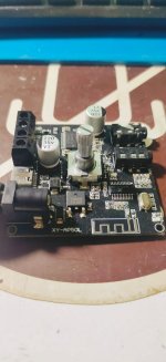
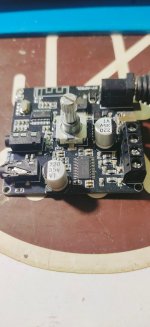
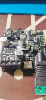
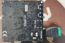
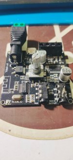
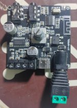
while searching i found this post and want to ask a question ..how for encoder to be used with analog signal to make volume control ...ive this board from aliexpress its 2 channel stereo class-d amplifier and i cant find any chips but the amplifier it self and the bluetooth chip how to run the encoder such a way?
Attachments
- Home
- Source & Line
- Analog Line Level
- Preamp Control - Volume, input, mute, remote