I'm choosing between various relays for the sake of input/signal switching.
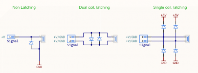
I'm attempting to get my head around the simplest methods of protecting against back EMF using diodes on various relays. I've mocked up some quick dummy schematics to illustrate what I understand so far (transistors not present for the sake of clarity) - see the first attachment.
A. Non-latching
Easy - a single reverse biased diode across the coil terminals.
B. Dual coil, latching
Two diodes, biased in opposite directions. When the signals change polarity, there is always a reverse-biased diode across the coil terminals. Also fairly simple.
C. Single coil, latching
Here's where things get tricky - in my diagram, I referenced this answer on StackExchange, which provided the attached circuitLab example (attachment 2).
...
1. Is this arrangement of diodes for the third configuration - single coil, latching - correct?
2. And if so, how exactly does this work?
Attachments
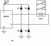
I am surprised that your microcontroller's I/O pins have enough "grunt" to directly drive the coil of a relay. The lowest-current "5 volt" relay coil sold at distributors seems to be 10mA, while the lowest-current "3.3 volt" relay coil sold at distributors seems to be 11.7mA. That's a lot of current for a dinky little uC! I would have expected to see an NPN transistor between the uC I/O pin, and the relay coil.
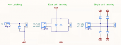
The "dual coil" diagram in Figure 1 of post #1, is doomed. The two diodes prevent the coil voltage from exceeding 0.7 volts, in either direction, which means the relay cannot pull in.
However the "single coil latching" diagram, will work. The four diodes clamp any flyback pulses that may occur, when you cut off the current path to the relay coil, preventing any voltage from exceeding the supply by more than 0.7V.
When the uC turns its I/O pins off, the dI/dt is about (10mA / 10nsec) = 1 million amperes per second. The good ole inductor equation tells us Vinductor = L * dI/dt so for any real-world value of coil inductance L, Vinductor is going to be many hundreds of volts. That's the Flyback voltage and it will certainly destroy your uC unless you take steps to clamp it.
Thanks Mark!
^ In my initial post I mentioned that I omitted the transistors for the sake of visual simplicity. No worries on that front.
Doh! Updated image attached. Brain fart.
Okay, thanks for this. I guess I'm still not intuitively getting precisely how this configuration works, but thanks for pointing me in the right direction. Are there any other typical usage scenarios where diodes are arranged like this for the sake of clamping voltages?
I am surprised that your microcontroller's I/O pins have enough "grunt" to directly drive the coil of a relay. The lowest-current "5 volt" relay coil sold at distributors seems to be 10mA, while the lowest-current "3.3 volt" relay coil sold at distributors seems to be 11.7mA. That's a lot of current for a dinky little uC! I would have expected to see an NPN transistor between the uC I/O pin, and the relay coil.
^ In my initial post I mentioned that I omitted the transistors for the sake of visual simplicity. No worries on that front.
The "dual coil" diagram in Figure 1 of post #1, is doomed.
Doh! Updated image attached. Brain fart.
However the "single coil latching" diagram, will work. The four diodes clamp any flyback pulses that may occur, when you cut off the current path to the relay coil, preventing any voltage from exceeding the supply by more than 0.7V.
Okay, thanks for this. I guess I'm still not intuitively getting precisely how this configuration works, but thanks for pointing me in the right direction. Are there any other typical usage scenarios where diodes are arranged like this for the sake of clamping voltages?
Attachments
When the uC turns its I/O pins off, the dI/dt is about (10mA / 10nsec) = 1 million amperes per second. The good ole inductor equation tells us Vinductor = L * dI/dt so for any real-world value of coil inductance L, Vinductor is going to be many hundreds of volts. That's the Flyback voltage and it will certainly destroy your uC unless you take steps to clamp it.
I have found PIC micro's to be quite hardy.
On a few projects I have put in mains voltage through a high value resistor with no problems into an i/o pin.
PIC's have diodes to the rails anyway so will take a bit of stick.
What is the cost/benefit of omitting a relay-driving transistor and flyback diode when you use a PIC microcontroller to operate a relay?
A few pence for diode, transistor and a couple of resistors plus pcb space saved.
The dual coil schematic would be clearer if you drew two coils.
For the non-latching case, you can speed up the switching off of the relay by connecting a Zener diode in anti-series with the freewheeling diode. That can improve the relay reliability when its contacts are heavily loaded (which is not the case for audio line input switching).
For the non-latching case, you can speed up the switching off of the relay by connecting a Zener diode in anti-series with the freewheeling diode. That can improve the relay reliability when its contacts are heavily loaded (which is not the case for audio line input switching).
Last edited:
A few pence for diode, transistor and a couple of resistors plus pcb space saved.
The disadvantage is potential latch-up and resulting destruction of the microcontroller, if the peak current exceeds the latch-up rating. Then again, latch up is usually tested with 100 mA and many relays will stay well below that.
- Status
- This old topic is closed. If you want to reopen this topic, contact a moderator using the "Report Post" button.
- Home
- Source & Line
- Analog Line Level
- Protection diodes for various relay types?