Hi there,
I am working on a circuit which converts Balanced signal to Unbalanced signal. I also attenuate the signal 12 dB. I have the schematics with op amps working perfectly.
Naked version here:
But since I want to make it a professional audio circuit, I would like to know what should I add it, like bypass capacitors. I am not an engineer but learning these things, so I would appreciate all help.
Here is my final version with bypass capacitors and 10K input resistors.
I would appreciate a lot if you can suggest me if I need to use DC removal or not, or how to use, or what else I need more on the circuit.
Thanks...
I am working on a circuit which converts Balanced signal to Unbalanced signal. I also attenuate the signal 12 dB. I have the schematics with op amps working perfectly.
Naked version here:
An externally hosted image should be here but it was not working when we last tested it.
But since I want to make it a professional audio circuit, I would like to know what should I add it, like bypass capacitors. I am not an engineer but learning these things, so I would appreciate all help.
Here is my final version with bypass capacitors and 10K input resistors.
An externally hosted image should be here but it was not working when we last tested it.
I would appreciate a lot if you can suggest me if I need to use DC removal or not, or how to use, or what else I need more on the circuit.
Thanks...
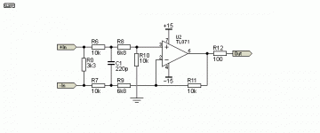
Far too complex. All you need is this basic design, as most manufacturers of high quality mixing desks use. By all means use 'better quality' op amps but it is difficult to beat a TL071.
Extra buffering is not normally required.
You can attenuate as you with.
Extra buffering is not normally required.
You can attenuate as you with.
Attachments
You can also just use a dedicated converter. Performance of THAT1200 is very good.
http://www.thatcorp.com/datashts/THAT_1200-Series_Datasheet.pdf
http://www.thatcorp.com/datashts/THAT_1200-Series_Datasheet.pdf
Far too complex. All you need is this basic design, as most manufacturers of high quality mixing desks use. By all means use 'better quality' op amps but it is difficult to beat a TL071.
Extra buffering is not normally required.
You can attenuate as you with.
That will 'work' but the 3 op amp design will be quieter - due to both lower value resistors where it matters and less voltage noise from that opamp.
Yes - mixing desks often had loads of TL07x op amps inside but generally that was due to cost and reliability considerations as there are hundreds of them and the NE5532 or NE5534 bipolar devices used to cost loads more and
have significantly higher power consumption causing thermal issues and requiring uprated power supplies.
When you're building something DIY and using only a few op amps you probably don't have the same constraints.
For the OPs circuit - probably want small caps across R2 / R3 (I think - can't see schematic atm) to limit the bandwidth. And need to consider where the output is going - if driving any length of cable you need to include a series output resistor for stability with capacative loads eg a screened cable - say 51R to 100R
Yeah - read Self if you can - clearer than web forum posts - but you've got it pretty much right assuming your voltage rails are okay for noise etc.
Define your environment.
Loooong lines in adverse places (recording mosquitoes in an electrical factory), you may need extreme input impedances. 1Meg differential and >1Meg CM.
But in one-building studio complexes, the 1-opamp 4-R diff-input works plenty good; when it doesn't, you have an Odd Problem and probably need a transformer.
Then you MUST always apply basic audio hygiene. Assume your source leaks DC. Assume your destination has a lot of capacitance. Assume your power supply is full of crap. Assume the idiot user will adapt a power amplifier to the input. Assume WNBC-AM tower is right next door. Input caps and resistors, output caps and resistors, power rail caps and resistors.... What Could Go Wrong?
The idea of "Always working OK, or at least not burnt" trumps most quibbles about nanoVolt hiss or cascaded stages.
Why cant we just use a single 5534 in differential mode?
Already hit-upon......
All you need is this basic design, as most manufacturers of high quality mixing desks use. ...
Yes, the one opamp plan works in most situations.
In *adverse* situations (not most hi-fi), the single amp plan has several impedances for each input, differential and common-mode, spoiling ideal performance.
Opamps are cheaper than the connectors. _IF_ more amps matter, why quibble?
...look to what Douglas Self has written....
Doug Self is *always* good reading. Read the Masters before asking general questions.
More specifically, DM and CM input impedance are intrinsically linked, and they are linked to noise level as well. You can't increase CM impedance beyond a certain point without introducing rather more noise than is commonly deemed acceptable.In *adverse* situations (not most hi-fi), the single amp plan has several impedances for each input, differential and common-mode, spoiling ideal performance.
The 3-opamp circuit allows reducing impedance levels to whatever the ICs will comfortably drive while still providing high input impedance. CM input impedance can even be increased further by using a T-type input bias arrangement, potentially into the megohms. The same can be done with RF suppression capacitors to keep up CM input impedance at high frequencies.
One problem of typical "3-opamp" variable gain instrumentation amplifier ICs in this application deserves mention: They are not suitable for gains of less than unity. They tend not to have particularly low noise at low gains either (70-100 nV/sqrt(Hz) @ Gv = 1, typ - the THAT12xx line receivers have that beat by anywhere from 6 to 10 dB).
In mass production I'd probably combine THAT1286 / INA2137 @-6 dB with opamp input buffers. (This would match common balanced output circuitry with a gain of 6 dB. I guess you could use the corresponding 0 dB parts and follow them up with external attenuation if you need even lower noise.) For one-offs, manual resistor matching should do just fine, and you get to choose values and ratio and opamp type as a bonus.
Why cant we just use a single 5534 in differential mode? Legitimate question here
This is a short article I wrote comparing a single op amp in a difference amplifier circuit, to a 3-op amp solution. In this case the 3-op amp solution was an integrated chip, the INA1650.
http://www.ti.com/lit/an/slyt737/slyt737.pdf
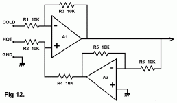
try to use superbal circuit. I was very satisfied with that topology.
Fig 12 from Balanced Line Technology - VPN Security
cheers
Fig 12 from Balanced Line Technology - VPN Security
cheers
Attachments
- Status
- This old topic is closed. If you want to reopen this topic, contact a moderator using the "Report Post" button.
- Home
- Source & Line
- Analog Line Level
- Balanced to Unbalanced Converter Help!

