What happens when a panel of strangers in a carefully controlled test (or John Atkinson of Stereophile - I am a subscriber!), prefers something that, subjectively, sounds like crap to you?
The controlled test I had in mind would not determine preference, it would determine if there were an audible difference. Hence, the above would never occur.
edit: Ok, what the heck. Lets say you did do a test for preference. I have not found my preferences differ from typical all that much, so again, that result is highly unlikely.
Last edited:
In other words, you subjectivity and expectation bias are not insurmountable, allowing your personal opinion to be not-so-erratic and to provide reasonably consistent, repeatable results, making it a useful navigation tool. With it, you don't need to blindly trust anyone's opinion, because you can have your own by building, measuring, listening, and sharing your experience. It costs parts and time, but it moves you up the learning curve, reducing you subjectivity and expectation bias along the way. It is also funI have not found my preferences differ from typical all that much, so again, that result is highly unlikely.
")
“In other words...”. I didn’t say anything like that at all. I’m sorry if my post was confusing.In other words, you subjectivity and expectation bias are not insurmountable, allowing your personal opinion to be not-so-erratic and to provide reasonably consistent, repeatable results, making it a useful navigation tool. With it, you don't need to blindly trust anyone's opinion, because you can have your own by building, measuring, listening, and sharing your experience. It costs parts and time, but it moves you up the learning curve, reducing you subjectivity and expectation bias along the way. It is also fun
So, to clarify: expectation bias is only surmounted when it is eliminated by blind testing. Sighted, biased, personal opinion easily becomes erratic when the external stimulus changes, and is of itself not given to repeatable results apart from the source of bias.
Biased personal opinion based on fully sighted listening in any environment must include the effects of bias, and the results cannot be separated from that bias.
Building something, with the investment of time and money, does absolutely nothing to reduce subjectivity and expectation bias, as the process itself is by its nature laden with expectation.
It seems there may be a gap in understanding of the meaning and concepts of controlled testing, subjective and objective evaluation, and how to benefit from each. I suggest starting with “High-Resolution Subjective Testing Using a Double-Blind Comparator” by David Clark, JAES Volume 30 Issue 5 pp. 330-338; May 1982. He outlines the need for such testing, test and analysis methods and controls, centering on how to obtain good objective data from subjective listening tests.
Hi,
I have two of the PGA2310 boards and have built one. The sound is great and I see that much of the bass that appeared to be missing previously was probably a dac/amp mismatch. But over the top of that wonderful new sound is some serious static.
Twisted pair opus to PGA2310 board via balanced cable. PGA2310 to Truepath amp via ground sensing single ended connection.
If I unhook the ground sensing wire from the Truepath and just connect the grounds directly the static goes from horrible to OK but something to work on.
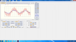
I hauled out my cheap USB oscilloscope and amp on or off makes no difference. The signal looks good into the 2310 board. On the attached screenshot, blue is the input and red is the ground sense output. Both channels had similar behavior.
The actual 2310 is one that I got from a forum member that he was not using. It is the surface mount variety and I used an adapter.
I have tried the arduino controller with both the built in 5v and a usb power supply and it makes no difference in the noise.
Any ideas?
Andy
I have two of the PGA2310 boards and have built one. The sound is great and I see that much of the bass that appeared to be missing previously was probably a dac/amp mismatch. But over the top of that wonderful new sound is some serious static.
Twisted pair opus to PGA2310 board via balanced cable. PGA2310 to Truepath amp via ground sensing single ended connection.
If I unhook the ground sensing wire from the Truepath and just connect the grounds directly the static goes from horrible to OK but something to work on.
I hauled out my cheap USB oscilloscope and amp on or off makes no difference. The signal looks good into the 2310 board. On the attached screenshot, blue is the input and red is the ground sense output. Both channels had similar behavior.
The actual 2310 is one that I got from a forum member that he was not using. It is the surface mount variety and I used an adapter.
I have tried the arduino controller with both the built in 5v and a usb power supply and it makes no difference in the noise.
Any ideas?
Andy
Attachments
The first thing that comes to my mind is EMI. The board has no built-in EMI protection on any of its inputs - I intended to have them close to external connectors so as to prevent EMI ingress into the box.
If there is no EMI filters close to external connectors, or if an EMI source (e.g. Class D amp and/or SMPS) are in the same box as the volume control, these inputs are susceptible to EMI ingress. EMI can also enter from the powerline though a linear power supply, e.g if powerline ethernet adapters are being used nearby.
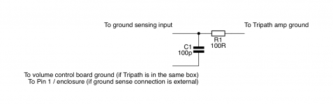
In particular, the ground sensing input (the right end of R24/R46 on the schematic) is an input with no EMI protection. If my guess about EMI is correct, a simple RC filter on the ground sensing input (see the attached schematic - the values are not critical) may help. You can place it directly on the output pads of the volume control board. If it helps with the static, it probably makes sense to add similar filters on each of the signal inputs, both "hot" and "cold".
Another possibility is something oscillating - the red trace on your screenshot may be ~40kHz oscillation on top of audio signal. I have not seen this in my testing, and to make a reasonable guess, I would need to better understand your setup. It would help if you could clarify if your power amp is in a separate or the same box as the volume control and post a photo of your setup.
If there is no EMI filters close to external connectors, or if an EMI source (e.g. Class D amp and/or SMPS) are in the same box as the volume control, these inputs are susceptible to EMI ingress. EMI can also enter from the powerline though a linear power supply, e.g if powerline ethernet adapters are being used nearby.
In particular, the ground sensing input (the right end of R24/R46 on the schematic) is an input with no EMI protection. If my guess about EMI is correct, a simple RC filter on the ground sensing input (see the attached schematic - the values are not critical) may help. You can place it directly on the output pads of the volume control board. If it helps with the static, it probably makes sense to add similar filters on each of the signal inputs, both "hot" and "cold".
Another possibility is something oscillating - the red trace on your screenshot may be ~40kHz oscillation on top of audio signal. I have not seen this in my testing, and to make a reasonable guess, I would need to better understand your setup. It would help if you could clarify if your power amp is in a separate or the same box as the volume control and post a photo of your setup.
Attachments
Last edited:
Thanks Alex.
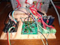
I will keep plugging away at things and try your suggestions. I have included some photos, I just have things screwed to plywood now. Truepath is powered by two LRS350 Mean Well SMPSs. Opus and volume board use linear supplies. I looked at the power going into the volume board and it was very clean. Also, I forgot to tell you the noise level does not change as I adjust the volume. Opus direct to Truepath worked fine for years and was very quiet (I used 2 Truepaths bridged to use balanced Opus output).
I was kind of hoping you wouldn't ask for photos of my setup it is kind of a cluster right now. I will work on this in between about a thousand other things that are more important, so I might be a little slow responding, but I appreciate the help.
Andy
I will keep plugging away at things and try your suggestions. I have included some photos, I just have things screwed to plywood now. Truepath is powered by two LRS350 Mean Well SMPSs. Opus and volume board use linear supplies. I looked at the power going into the volume board and it was very clean. Also, I forgot to tell you the noise level does not change as I adjust the volume. Opus direct to Truepath worked fine for years and was very quiet (I used 2 Truepaths bridged to use balanced Opus output).
I was kind of hoping you wouldn't ask for photos of my setup
it is kind of a cluster right now. I will work on this in between about a thousand other things that are more important, so I might be a little slow responding, but I appreciate the help.Andy
Attachments
Thank you for the photos - the setup looks very neat to me
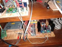
Looking at those twisted pairs connecting the volume control to the power amp, I think they may present enough capacitance to the output opamp of the volume control to make it oscillate. The cable capacitance between the output and ground cancelling input creates frequency dependent positive feedback for the opamp, which may lead to oscillation. One remedy would be to replace the twisted pair and a separate ground wire with two lengths of shielded cable, one for signal, one for ground sensing. These two signals are not a balanced pair, and separate shielding will dramatically reduce capacitance between them.
Also, may I ask for one more clarification: when you were taking the traces with your scope, where did you connect the ground clip of the scope - to the power amp's ground or to the volume control's GND pad? If you connect the scope between OUT and GND pads on the volume control, you will see the sum of your audio signal and the ground cancellation signal. The correct way is to connect the scope in parallel with the power amp's input.
Last edited:
I did some additional simulation and testing on an actual ground sensing output stage with both NE5532 and LM4562. It generally confirmed my guesses from the two posts above, but also indicated that the problems I thought about are probably not likely to occur in a reasonable setup such as yours.
The test setup consisted of a volume controller with the output of one channel configured for ground sensing. I connected three unreasonably long (~10ft/3m) unshielded wires to the ground, output, and ground sense input pads of the channel in question.
I realized it makes sense to mount R26/R48, the 22ohm resistor connecting the ground sense input with the ground. This input is meant to be low impedance, so this resistor should be there in both balanced output and ground sense configurations. Testing was done with R26/R48 in place.
First, I tested an NE5532 (typical GBP=10MHz). I did observe more noise with long unshielded wire at the input, but there was no obvious RFI problem or instability. NE5532 could be made to oscillate in 100s of kHz range if the ground sense input was connected to the output with a capacitor in 1..10nF range directly at the board's pads. Caps smaller than ~1nF did not result in oscillation, although with values in 100s of pF, the phase margin was probably reduced.
Second, I plugged in an LM4562 (typical GPB=55MHz). I observed RFI in MHz range, which I suppressed with an RC filter as described in the post #86. With 10ft wires, there was an intermittent oscillation (with and without RC filter), also in MHz range, dependent on the mutual position of the wires and on whether the far end of the ground sense wire was connected to the far end of ground wire. Replacing the unshielded ground sense wire with shielded eliminated instability.
Third, I cut my long wires to a length similar to what I see in your photos, about 20in/50cm, and saw no sign of instability or RFI, even without RC filter and unshielded wires.
Note that I did not observe anything similar to the ~40kHz signal that was clearly visible on your scope, nor could I make the board oscillate around that frequency with either opamp. I would guess that that signal must be specific to your setup. (What is the switching frequency of your Mean Well SMPS?)
When you have a chance, please let us know what you found in your setup.
Last edited:
(What is the switching frequency of your Mean Well SMPS?)
That is the point
Alex, the docs and build help were great and the build went easily. Only two minor problems that I could remember.
The 22 ohm resistors called out in your parts list are 2x the size of the other resistors. They don't match the holes in the board and you have to mount them a bit above.
There seem to be two choices for the first capacitor (c3/c4) on the power coming into the board. No real explanation on which to use, I spent a while trying to track down if I was making a mistake or missed something before I decided it probably isn't a big deal.
Thank you and apologies for the problems.
I updated the schematic and corrected both the BOM and the shared project at Mouser.
I updated the schematic and corrected both the BOM and the shared project at Mouser.
Last edited:
alexcp, thanks for your marvelous work!
One question on the schematic with the MUSES volume control found here:
https://cdn.shopify.com/s/files/1/0077/4828/8576/files/bvc_gs_muses_sch.pdf?24
What would happen if you omit the capacitors C26-C29? I have seens schematics with the exact same volume control chip that didn't use them at all and connected the pins straight to ground. I know that they are supposed to be there according to the datasheet, so just asking...
The caps are preventing DC current from flowing through the digital attenuators in the MUSES chip. The datasheet adds another cap between the MUSES chip and the non-inverting input of U6 if U6 has bipolar input (see bottom of page 10 of the datasheet, "Application circuit with Bipolar Input type OpAmp"). Bipolar input opamps typically have nanoamp range input currents, compared to picoamps for JFET input opamps, and the datasheet takes care to block these nanoamps from flowing through the chip.
Some people like to short the caps on account of caps in general being bad for sound. I myself have NOT tested the circuit with the caps shorted. My guess is that nothing evil should happen. Any input DC is removed by the HPF (U4), and the DC voltage across the attenuators is limited to the (small, typically 1mV or less) DC offsets of U5/U8 and U6. The worst case scenario is probably having audible clicks at the output when changing volume. Again, I have not tested this.
I have seen reports where shorting the input cap (C26/C28) led to audible distortion which would not go away until the cap was replaced with a resistor. I have not got to the bottom of this so can't say what was at play.
I'd say try to build it without the caps - you can always add them later if you feel you need them.
As announced in my last post, here is one more volume controller. This one is based on the DS1882 digital pot, with the output buffered by matched JFETs, B1/Mezmerize style. The digital potentiometer, two JFET buffers and their analog power supply regulators are mounted on one 1100x1100mil (28x28mm) board.
Real good design,can you share the gerber file? thanks again.
Best regards
Leo
Alex, I have another question: The caps in the DC nulling circuit (C16, 17, 18...) are shown as unpolarized 10uF caps in the schematic. The BOM shows them as polarized 50V aluminium electrolytic caps. Which way will the be populated around? Or does this not matter? What about if the input delivers some constant DC on both +/- balanced input lines, like for example a DDDAC with a resistor as "I/V" like my friend has one? Do I have to care for polarity then?
- Home
- Source & Line
- Analog Line Level
- Balanced Volume Controller / Line Stage