I doubt you could really satisfy everybody here, the best you'll be able to do is offer some prescribed 'breakouts' for users to mix and match.
The current look I am working to in my project is the late 80's digital theme. In that case the panel buttons would be tactile switches only if there will be any, however like the real equipment everything is done using the remote in practice anyway.
Furthermore - with displays - a point of contention for these projects is where the information is coming from. Sure your volume control knows the volume setting, but if a user then wants to show information like track time from media server XYZ or FOTM service box ? The user really has to take responsibility for making that bridge. You can only go so far with your model cases before it becomes frustratingly unsupportable and inconsistent in quality.
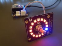
Exact feelings here. I like the little board attached to the rotary encoderFurthermore - with displays - a point of contention for these projects is where the information is coming from. Sure your volume control knows the volume setting, but if a user then wants to show information like track time from media server XYZ or FOTM service box ? The user really has to take responsibility for making that bridge. You can only go so far with your model cases before it becomes frustratingly unsupportable and inconsistent in quality.
In my design, I used an LED ring around the encoder that is mounted on the PCB. A micro controller updates the ring based on the digital level. It works well for me. Some details here: preamp-two/images/prototypes at master * FutureSharks/preamp-two * GitHub
Attachments
Please, is this needed or even sound, in a thread about electronic volume controls?Seems more like trolling.I got away with regulating the volume electronically. All chips have too much distortion. Even the expensive ones. Furthermore, the rotary have no end stop. Bad usibility.
I put a lot of money and time into the subject, but electronic pots didn't meet my expectations. But that should not stop you.Please, is this needed or even sound, in a thread about electronic volume controls?Seems more like trolling.
May I ask you to share your expectations, and how digital ports did not meet them?[...]electronic pots didn't meet my expectations
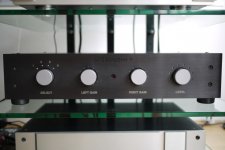
I am not specifically advocating digital pots; in fact, the volume control that started this thread is fully analog with a mechanical dual potentiometer sticking out of the board. However, I am interested in what makes both digital and analog controls perform better (or worse) sonically. Perhaps your experience would help others better understand the tradeoffs.
May I ask you to share your expectations, and how digital ports did not meet them?
I am not specifically advocating digital pots; in fact, the volume control that started this thread is fully analog with a mechanical dual potentiometer sticking out of the board. However, I am interested in what makes both digital and analog controls perform better (or worse) sonically. Perhaps your experience would help others better understand the tradeoffs.
I would be interested in the specific method used to determine a control is "better" or "worse".
It is an interesting discussion that may lead away from volume controls.
My view is that we are talking about entertainment, and the ultimate criterion is "better" or "worse" entertainment. It is subjective, of course (Nelson Pass commented somewhere that the brightness of front panel LEDs on his FirstWatt amplifiers affected the perceived amplifier performance). I asked diyralf about expectations in an attempt to figure out what part of entertainment was missing") .
.
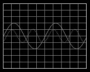
Moving from subjective performance to engineering, the major factor seems to be distortion - although not only the THD+N @ 1kHz. For example, Vladimir Lamm of LAMM Industries, a successful maker of expensive hifi gear, suggests, based on his primary research, ideal distortion measurements (see pics below), which focus on distortion as a function of frequency and volume, as well as on distortion spectrum. The special PCB layout in my balanced volume controls is specifically designed to control HF distortion. (BTW, measuring THD+N @ 20kHz is useful, but if a soundcard is all you have, a two-tone test - say, 19kHz+20kHz - is a good proxy.)
My view is that we are talking about entertainment, and the ultimate criterion is "better" or "worse" entertainment. It is subjective, of course (Nelson Pass commented somewhere that the brightness of front panel LEDs on his FirstWatt amplifiers affected the perceived amplifier performance). I asked diyralf about expectations in an attempt to figure out what part of entertainment was missing
.Moving from subjective performance to engineering, the major factor seems to be distortion - although not only the THD+N @ 1kHz. For example, Vladimir Lamm of LAMM Industries, a successful maker of expensive hifi gear, suggests, based on his primary research, ideal distortion measurements (see pics below), which focus on distortion as a function of frequency and volume, as well as on distortion spectrum. The special PCB layout in my balanced volume controls is specifically designed to control HF distortion. (BTW, measuring THD+N @ 20kHz is useful, but if a soundcard is all you have, a two-tone test - say, 19kHz+20kHz - is a good proxy.)
Attachments
There are many criteria for a good level control. E.g. offness, THD at higher frequencies, what happens at 10Vrms input, L / R deviation at large and very small levels, etc.? Electronic solutions fail here on some points, other solutions on others. You have to know what's important to you.
With LM4562s and regulators onboard, each board draws about 70mA from each rail; negative rail takes slightly less.
One LM4562 draws about 10mA, see figures 102-104 on page 21 in its datasheet (NE5532s may take slightly less depending on the make); PGA2310 takes about 7-8mA per rail; and each regulator needs about 5-6mA of quiescent current.
With the onboard 12..15V regulators bypassed, I would expect it to be 5-6mA less on each rail.
This consumption doesn't include the controller (e.g. an Arduino) that can be powered with 5V from the 8-pin connector.
Subjective data can be analyzed objectively if collected properly. For example, you can analyze the perceived audible impact of the brightness of the front panel led by making it the single variable in an ABX test with sufficient tests and testers.It is an interesting discussion that may lead away from volume controls.
My view is that we are talking about entertainment, and the ultimate criterion is "better" or "worse" entertainment. It is subjective, of course (Nelson Pass commented somewhere that the brightness of front panel LEDs on his FirstWatt amplifiers affected the perceived amplifier performance). I asked diyralf about expectations in an attempt to figure out what part of entertainment was missing
If you're speaking of the audibility of distortion, then it's still subjective. Engineering and subjectivity do not exist in isolation of each other.Moving from subjective performance to engineering, the major factor seems to be distortion - although not only the THD+N @ 1kHz.
But that's not new, nor peculiar to him. Though not typically published, any audio developer will have done distortion vs frequency and level tests. It's quite easy to do with modern test methods. But those test results are not published because they comprise a rather large amount of data that really can only be charted on a 3D graph, which is hard for the typical consumer to assimilate, hence the published single-figure THD spec, easier to understand, but also meaningless.For example, Vladimir Lamm of LAMM Industries, a successful maker of expensive hifi gear, suggests, based on his primary research, ideal distortion measurements (see pics below), which focus on distortion as a function of frequency and volume, as well as on distortion spectrum.
The tests and measurements are objective, the audibility of the results are subjective. Particularly so if one considers that the audibility of harmonic distortion products depends on the specific spectrum of the distortion products AND how they may be masked by the musical signal. For example, there is ample evidence that suggests relatively strong amounts of even-order distortion products are necessary before they reach audibility, yet lower amounts of odd-order harmonics are objectionable, though even that is a gross simplification.
Please elaborate on how a PCB layout affects HF distortion.The special PCB layout in my balanced volume controls is specifically designed to control HF distortion.
A good many soundcards can be set to sample at 192kHz these days, making 20kHz THD measurable to the 4th harmonic possible. Useful? Not too sure about that. Multi-tone signals at high frequencies may have more relevance to the audibility of nonlinearities because the distortion products fall easily mid-band, and in relative frequency isolation of the stimulus (the difference product of 19kHz and 20kHz is 1kHz, easy to measure and hear, whereas the third harmonic of 20kHz is 60kHz, which is impossible to hear). I don't think conventional THD measurements above 10kHz have a lot of meaning in terms of audibility of distortion because the distortion products fall outside the range of human hearing. However, whatever nonlinearity causes higher THD will also likely cause IMD, and IMD products can become quite audible even when the signals being distorted are just outside of the audible frequency range. There is validity to looking at multi-tone tests done above 20kHz, and especially between 10kHz and 20kHz. The paper I like to refer to on this is "Spectral Contamination Measurement" by Jensen and Sokolich, JAES, November 1988.(BTW, measuring THD+N @ 20kHz is useful, but if a soundcard is all you have, a two-tone test - say, 19kHz+20kHz - is a good proxy.)
Thank you jaddie for elaborating on there topic. Didn't I say it is an interesting discussion that may lead away from volume controls?
Regardless of how you measure it, distortion rising with frequency has an audible sonic signature, recognizable as tight or controlled bass. In a feedback amplifier, two contributors to distortion rising with frequency are (1) lack of HF loop gain and (2) errors in the feedback loop.
Lack of HF loop gain is particularly conspicuous when gain-bandwidth product (GBW) is low and gain is high, as in a power amplifier. With GBW fixed, second- and higher-order feedback loops and composite amplifiers help improve HF loop gain. You can also throw away some LF gain ("reducing feedback") to make distortion level vs frequency more uniform and thus less offensive. The volume controls that are the subject here, however, use LM4562 with GBW=55MHz at unity gain, still providing about 70dB of loop gain at 20kHz, which makes lack of loop gain much less of an issue.
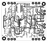
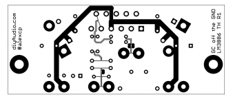
Errors in the feedback loop are construction dependent, and here is where the PCB layout and routing become crucial. Noise and non-linear currents from e.g. power supplies couple into signal and feedback loops, and coupling increases with frequency. To deal with this, I explicitly treat each signal as a pair of wires routed together and place all components in pairs, thus minimizing the area between the signal and its reference. This way, any interference affects both signal and the reference equally and becomes a common mode signal, which LM4562 with CMRR=120dB rejects.
BTW, I previously applied the same construction technique to LM3886 based power amplifier with excellent results.
Regardless of how you measure it, distortion rising with frequency has an audible sonic signature, recognizable as tight or controlled bass. In a feedback amplifier, two contributors to distortion rising with frequency are (1) lack of HF loop gain and (2) errors in the feedback loop.
Lack of HF loop gain is particularly conspicuous when gain-bandwidth product (GBW) is low and gain is high, as in a power amplifier. With GBW fixed, second- and higher-order feedback loops and composite amplifiers help improve HF loop gain. You can also throw away some LF gain ("reducing feedback") to make distortion level vs frequency more uniform and thus less offensive. The volume controls that are the subject here, however, use LM4562 with GBW=55MHz at unity gain, still providing about 70dB of loop gain at 20kHz, which makes lack of loop gain much less of an issue.
Errors in the feedback loop are construction dependent, and here is where the PCB layout and routing become crucial. Noise and non-linear currents from e.g. power supplies couple into signal and feedback loops, and coupling increases with frequency. To deal with this, I explicitly treat each signal as a pair of wires routed together and place all components in pairs, thus minimizing the area between the signal and its reference. This way, any interference affects both signal and the reference equally and becomes a common mode signal, which LM4562 with CMRR=120dB rejects.
BTW, I previously applied the same construction technique to LM3886 based power amplifier with excellent results.
Attachments
While I do not question the existence of these mechanisms, I do strongly question their audibility. Please understand, I'm not saying your claims here are not true, but they do raise some questions.Thank you jaddie for elaborating on there topic. Didn't I say it is an interesting discussion that may lead away from volume controls?
Regardless of how you measure it, distortion rising with frequency has an audible sonic signature, recognizable as tight or controlled bass. In a feedback amplifier, two contributors to distortion rising with frequency are (1) lack of HF loop gain and (2) errors in the feedback loop.
Lack of HF loop gain is particularly conspicuous when gain-bandwidth product (GBW) is low and gain is high, as in a power amplifier. With GBW fixed, second- and higher-order feedback loops and composite amplifiers help improve HF loop gain. You can also throw away some LF gain ("reducing feedback") to make distortion level vs frequency more uniform and thus less offensive. The volume controls that are the subject here, however, use LM4562 with GBW=55MHz at unity gain, still providing about 70dB of loop gain at 20kHz, which makes lack of loop gain much less of an issue.
Errors in the feedback loop are construction dependent, and here is where the PCB layout and routing become crucial. Noise and non-linear currents from e.g. power supplies couple into signal and feedback loops, and coupling increases with frequency. To deal with this, I explicitly treat each signal as a pair of wires routed together and place all components in pairs, thus minimizing the area between the signal and its reference. This way, any interference affects both signal and the reference equally and becomes a common mode signal, which LM4562 with CMRR=120dB rejects.
BTW, I previously applied the same construction technique to LM3886 based power amplifier with excellent results.
How can rising distortion at high frequencies (I assume, by HF we are talking 10-20kHz and above?) be heard as affecting bass?
How have you evaluated the audibility of HF loop gain? I'm asking specifically about the evaluation/test method. And yes, the test method does matter.
The best way I know to address that is to build yourself several different boards, listen to them and tell us what you think you hear and what you think you don't hear. Never trust strangers' earsI do strongly question their audibility.
The best way I know to address that is to build yourself several different boards, listen to them and tell us what you think you hear and what you think you don't hear. Never trust strangers' ears
Um...no, that would be the worst way. Costly in terms of parts and time, and totally subjective and under the influence of full expectation bias.
This is precisely what I'm getting at. That kind of testing yields erratic and non-duplicatable results. If that's the kind of testing used to verify the theories above, then we have no proof.
You can trust strangers ears, provided the tests are carefully controlled and you have enough strangers. In fact, you need strangers to validate the test!
What happens when a panel of strangers in a carefully controlled test (or John Atkinson of Stereophile - I am a subscriber!), prefers something that, subjectively, sounds like crap to you?
- Home
- Source & Line
- Analog Line Level
- Balanced Volume Controller / Line Stage