When I first read this thread I took a piece of paper and drew up how I thought the circuit would have to work. Guess what? I was right and I'm no engineer. I also figured out without a problem that your little tweeks were a simple attempt to make someone think you had come up with something different. Which of course you haven't.
Son, you can draw up an extensive power supply with additional components extra filtering and such and you really haven't done a damn thing except over complicate things and add additional parts. The operation of the LDR is quite simple. The resistance changes with light I can prove that. The LED is separate from the resistance and I can prove that. Any thoughts as to the LED injecting any noise into the circuit that can be heard are pure horse hockey. The supposition that one design gives more bass or better sound stage is pure nonsense. Its called marketing hype. The circuit is simple the audio is routed thru a simple voltage divider and it acts like a pot with a wiper without actually having a wiper both sides of the divider change when you vary the intensity of the LED. Anything else is pure nonsense. The supply to the LED needs only not to fluctuate when the control isn't being turned.
Hell, maybe I should start selling a LDR control like this. I can throw in a couple of diodes in the power supply put it on a ground plane circuit board and claim it has a lower noise threshold. Count on my putting one of these together and when I'm done I'll take it to where I was employed for years and dig out some test gear and do some actual testing.
Oh dear! But have you heard what you think is the simplistic way you are guessing the stereo coffee uses circuitry ( which it plainly does not ) . Was it good or average sounding as an attenuator ? Refer to post 1, was that
description possibly different to your idea and resulting audio of your own built LDR attenuator. If it is then ask yourself is there a lot more to this
than you first presume. Your circuit description may just work but is vastly insufficient.
If you had a degree this might be interesting. Like I said added parts that contribute nothing. Just a different way of playing with the LED lighting that adds absolutely nothing to the audio simply because you cannot change the audio.
Well there you go, I hold the opposite view. Lets be thankful for that.
Nice meeting you on the forum
")
When I first read this thread I took a piece of paper and drew up how I thought the circuit would have to work. Guess what? I was right and I'm no engineer. I also figured out without a problem that your little tweeks were a simple attempt to make someone think you had come up with something different. Which of course you haven't.
Son, you can draw up an extensive power supply with additional components extra filtering and such and you really haven't done a damn thing except over complicate things and add additional parts. The operation of the LDR is quite simple. The resistance changes with light I can prove that. The LED is separate from the resistance and I can prove that. Any thoughts as to the LED injecting any noise into the circuit that can be heard are pure horse hockey. The supposition that one design gives more bass or better sound stage is pure nonsense. Its called marketing hype. The circuit is simple the audio is routed thru a simple voltage divider and it acts like a pot with a wiper without actually having a wiper both sides of the divider change when you vary the intensity of the LED. Anything else is pure nonsense. The supply to the LED needs only not to fluctuate when the control isn't being turned.
Hell, maybe I should start selling a LDR control like this. I can throw in a couple of diodes in the power supply put it on a ground plane circuit board and claim it has a lower noise threshold. Count on my putting one of these together and when I'm done I'll take it to where I was employed for years and dig out some test gear and do some actual testing.
How's your build developing ?
How's your build developing ?
Just a suggestion with your circuit, once you have it going, see if you can hear any difference at all between the NSL32SR2S LDr and the NSL32SR3
My experience and backed by manufacturers data, indicates the SR3 is the better of the two, so is the type I use, however higher measured resistance SR2S ,can indeed rival a SR3 with audio.
Looking forward to your findings.
Given this is a diyaudio forum how can such a thread be permitted without a posted schematic?
I think the answer to that, is the product was assembled as a diy kit, by the
person commencing the thread, which was at Post 1 simply letting us know
how it performed in their audio system.
Given this is a diyaudio forum how can such a thread be permitted without a posted schematic?
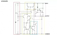
http://diyaudioprojects.com/Solid/DIY-Lightspeed-Passive-Attenuator/
Here is Georges schematic. Its pretty simple. The LED provides a light source and the light causes the photoresistors value to change. As you turn the pot one LED intensity rises and the other falls just like the voltage divider in the volume control pot.
My personal thought here would be to provide a control for each channel therefore you can tweek the balance.
With your multimeter measuring output to ground of a LM7805 can you inform of the resistance you find please. And does that suggest anything, or raise any question to you, or is there no question you can think of.
With your multimeter measuring output to ground of a LM7805 can you inform of the resistance you find please. And does that suggest anything, or raise any question to you, or is there no question you can think of.
Chris, could you please provide a plot of output impedance (magnitude and phase) vs frequency for your sample of LM7805 regulator?
Thanks.
I am just wondering how you use a multimeter to measure the 'resistance' of the output of a voltage regulator. I am also wondering what this has to do with audio.
Pretty easy I would of thought but ...
Place the Positive probe on the Out pin and the Negative probe on the Ground
pin, for a LM7805 what resistance do you measure ? Can that be answered
Yes/No
If your DMM is set to measure resistance and the regulator is powered, you will likely damage your DMM doing that. If the regulator is not powered, then you haven't measured anything meaningful.
Do you know how to measure the output impedance of an active device? (like measuring output Z of an amplifier.)
Do you know how to measure the output impedance of an active device? (like measuring output Z of an amplifier.)
7805 circuit diagram
Make your point Chris
That schematic fails to show the resistance from Output to ground
Even in Texas instruments latest schematic, it is vague because one
resistor called R20 has no stated value. http://www.ti.com/lit/ds/symlink/lm340.pdf
Measuring will however find the needed value, and to help you all out
as your multimeters cannot be found ? ..it is 4.79k
However different brands of 7805 differ, even from the same manufacturer
ST, I measured over 300% difference.
So placing a 7805 in a LDR circuit with accompanying capacitance, could we say its really a constantly powered R/C shunt circuit between anode and cathode, and signal ground ?
And could we say the 7805 constantly must preference its own internal fixed resistance, as a load, over anything else.... such as a sensitive LDR ?
The schematic at Post 127 has the cathode of the LDR at the same potentialSignal ground?
as signal ground
Chris, could you please provide a plot of output impedance (magnitude and phase) vs frequency for your sample of LM7805 regulator?
Thanks.
Figure 7 on Page 10 provides manufacturers data for output impedance vs frequency at 500ma, with Vin of 10v http://www.ti.com/lit/ds/symlink/lm340.pdf
I noticed that, it's a poor schematic where he's used the same ground symbols. However in the instructions they are not connected, and of course they shouldn't be.The schematic at Post 127 has the cathode of the LDR at the same potential
as signal ground
If we now step forward to escape the parallel 7805 device between anode and cathode
(with accompanying capacitance , fixed internal 7805 device resistance
and potentiometer necessary to have current being adjusted to cause
LDR signal side resistance being changed ) shown in Post 127
A dedicated current source for the anode, and a dedicated current sink for the cathode
becomes apparent as far a better approach. The clouds lift so to speak, to reveal what an LDR can actually do, as described in post 1 .
- Status
- Not open for further replies.
- Home
- Source & Line
- Analog Line Level
- Chris Daley's Stereo Coffee Preamp