An exact stepping is not needed, e.g. 0.6db, 0.8db, 0.5db, 1dB, .... doesn't matter. What matters is the channel equality! Less than 0.1 dB should be possible. That depends on the equality of the resistances. They should be pairwise measured before soldering
You do not have to match resistors in pairs before soldering.
I am using 0.1% resistors and the channel imbalance should be below 0.01dB, without matching resistors.
Still, to give a qualified advice I would still need so see a schematic of the circuit where he is trying to replace the Alps RK27.
Btw, Alps RK27 is a fine pot, probably one of the best log pots available. I used a 10K Alps RK27 until I switched to my own stepped attenuator.
Normally diy-er work with standard jelly bean parts. For metal res, 1% is common. Of course, 0.1% is better, but hard to source.
If you are using Thin Film resistors, 0.1% is the most common.
Mouser has 11K different 0.1% Thin Film resistors in stock, while they only have around 2K 1% Thin Film resistors.
Sure you could use Thick Film(Yuck) resistors, then 1% is the most commonly available resistor tolerance.
But then why build a high quality attenuator with almost perfect channel matching and then crapify it with higher distortion and higher noise Thick Film resistors?
There is a reason I have specified 1206 0.1% Thin Film resistors in the BOM.
You can get even better resistors but then the price starts to get unreasonable very fast.
Everything is a compromise, but using other cheaper and lower quality resistors just to save a few bucks is foolish, IMO.
BTW, the 1206 0.1% Thin Film resistors are only used in the signal path, in the control part of the attenuator 0805 1% Thick Film resistors are used. Different parts of the circuit require different tolerances and quality of components.
Last edited:
I do not know, do you have a schematic I can see? Without a schematic it is hard for me too know how much and what you might have to change.
But in general, from the output on this relay attenuator you need a resistance of 10K to GND. Otherwise the step size, depending on volume setting, will vary too much and not be exactly 0.6dB as intended.
Hope this simplified schematic is suffice...
Attachments
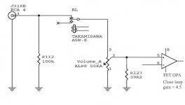
Hope this simplified schematic is suffice...
If R127(39K2) is the only thing that is connected to GND from the potentiometer output/+ Input on OPA then you would have to change R127 to 10K.
But it will work with 39K2, your step size just wont be 100% 0.6dB at all volume settings. It wont affect the channel balance, that stays the same no matter the resistor you use.
I use the wrong resistor value myself, 21K5, beacause I am using the attenuator with an older headphone amplfier I designed and it just doesn't bother me enough that it makes me want to change the resistor to 10K.

However, my new headphone amplifier is designed with this attenuator in mind and when it is done sometime later this year all will be well.
So to make it short, the optimal thing would be to change R127 to 10K but if you don't you most likely wont notice any difference anyway.
Last edited:
Oh, niiice, I saw this new version just now!
Can I slave an expander board to the main board, and offset the level of the expander board? I want to use the attenuator in a bi-amped system with an active line level crossover. Sensitivity matching for the woofer and tweeter could be done via a constant offset between the two boards...
I'm still happy with my v1 btw
Oh, niiice, I saw this new version just now!
Can I slave an expander board to the main board, and offset the level of the expander board? I want to use the attenuator in a bi-amped system with an active line level crossover. Sensitivity matching for the woofer and tweeter could be done via a constant offset between the two boards...
I'm still happy with my v1 btw
It is not possbile to make a digital offset between the Main attenuator board and the expander board.
However the attenuator has a constant(almost constant, it varies from 9K88 to 10K04) input impedance of 10K so if you added the correct value resistor in series with the signal input to the expander board then you would get an extra and constant attenuation of that particular signal.
Adding say, 10K in series with the input signal line would in conjunction with the attenuator impedance of 10K give a constant signal attenuation of 6dB.
Then you would just have to scale that resistor so you get the exact extra attenuation you want. Simple to do, creates slightly more noise, but everything is a trade off.
Nice that you are still using V1.
Hm, that might do the trick really.
I'm already using a high-ish impedance potential divider (buffered) at the output of the high pass to match the drivers' sensitivity. The V1 attenuator is currently at the input of the line level crossover. Moving the volume control to the output of the xover (4 "channels", LP and HP in stereo) should provide better SNR for the whole pre chain.
I'll think about it some more and will eventually place an order.
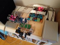
In the meantime, here's the V1 in action:
I'm already using a high-ish impedance potential divider (buffered) at the output of the high pass to match the drivers' sensitivity. The V1 attenuator is currently at the input of the line level crossover. Moving the volume control to the output of the xover (4 "channels", LP and HP in stereo) should provide better SNR for the whole pre chain.
I'll think about it some more and will eventually place an order.
In the meantime, here's the V1 in action:
Attachments
Hm, that might do the trick really.
I'm already using a high-ish impedance potential divider (buffered) at the output of the high pass to match the drivers' sensitivity. The V1 attenuator is currently at the input of the line level crossover. Moving the volume control to the output of the xover (4 "channels", LP and HP in stereo) should provide better SNR for the whole pre chain.
I'll think about it some more and will eventually place an order.
In the meantime, here's the V1 in action:
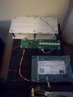
Here is V3
:Attachments
Hm, that might do the trick really.
I'm already using a high-ish impedance potential divider (buffered) at the output of the high pass to match the drivers' sensitivity. The V1 attenuator is currently at the input of the line level crossover. Moving the volume control to the output of the xover (4 "channels", LP and HP in stereo) should provide better SNR for the whole pre chain.
Another idea, why don't you just implement attenuation in your active line level xover? That should be easy to do.
Then you just have to build the attenuator + expander board connect them together and connect them at the output of your active line level xover.
EDIT : On second thought, sounds like that is what you are considering. It would make everything much easier and if you attenuate actively, you can get the impedances down and that also lowers the noise. Use an extra stage that drives a lowish impedance attenuator and then buffer the output before you send it to the attenuator.
I am just throwing out ideas and I have a lot of them.
There are many options.
Last edited:
If R127(39K2) is the only thing that is connected to GND from the potentiometer output/+ Input on OPA then you would have to change R127 to 10K.
Thank you for clearing up the doubts.
I have placed an order through PM.
I'm thinking maybe I should make a stackable interface board (with Bourns pot solder pads) in between attenuator and existing RK27 solder pads, eliminating all flying wires.
Looking forward to receiving my boards once the expanders arrive. I got my first consignment of parts yesterday - the Digikey resistors, I also got the relays and OPA191s from Digikey. Gosh, some of those parts are small! I'll be needing my 5x loupe I think. For the many-legged parts do you prefer to solder each leg individually or drag solder them? (Or have you got a reflow oven?)
Some of the components are very small. That is just the way it goes, all the good stuff comes in smaller and smaller packages. But I like that you can make smaller and more compact designs.
I solder each leg individually, but then again I am not an expert at soldering so others might find it easier to drag solder.
I solder each leg individually, but then again I am not an expert at soldering so others might find it easier to drag solder.
Last edited:
There is something that is unavoidable when relays are changing state.
Then what do I mean by that. Well since there is no zero crossing detection you might switch in relays at the top of the waveform which sometimes will give you a very small click or pop in the sound.
However this is not something you can avoid and it is also something all relay attenuators suffer from.
The good thing about this "feature" is that the maximum level of this click or pop is equivalent to your current volume setting. So there is zero risk of damage to your speakers or headphones.
So it is nothing like other suboptimal designs where you sometimes get maximum volume output when changing steps.
Some more info on how the attenuator works, from the V2 thread :
Simple really. If you were to control the realys without the Flip-flops you might risk having no attenuation at times when changing volume. Remember, when the realys are not turned on you have maximum attenuation, so when you turn up the volume you turn relays on and some off, but when you reach full volume, no attenuation, all relays are on. The problem is that realys do not make or break instantly, as an example, the realys I used has a make or break time of 3ms max, but it could be anywhere between ~1.5-3ms according to the datasheet.
Worst case is going from 1000000 to 0111111 where you might risk turning on all the LSB relays before you turn the MSB relay off. Basically you could risk it going from 1000000 to an intermediate value of 1111111 before you end up at your desired value of 0111111. 1111111 would be the same as no attenuation at all, not good.
By using 2 x octal flip-flops with their outputs fed into quad dual input and gates you can now control when the relays turn on and off.
Using the same example as above, you will now go from 1000000 to an intermediate value of 0000000 and end up at the final value of 0111111. Here 0000000 being full attenuation.
It is all about timing, you first take the realys that need to be turned off and turn them off and then 5ms after you turn on the relays that needs to be turned on. A full cycle take 10ms.
And :
Another thing that is unavoidable is what I call "temporary DC". This is because there is no zero-crossing detection and since you can't implement zero-crossing detection when using relays you have to live with the fact that the relays might switch ON at the peak of the waveform, which is going to sound like a very small pop. This is something that all attenuators based on relays have, even expensive high end commercial offerings with built in R-2R attenuators. Even my own attenuator sesign has that "feature".
I have 2 updates today.
1 : Those who have have ordered only the RA V3 PCBs, your orders will ship tomorrow.
2 : For those who have ordered both RA V3 and EXP V1 PCBs, I have just received shipping information for the EXP V1 PCBs and they should hopefully arrive this week.
With luck I can ship them out this coming Friday.
1 : Those who have have ordered only the RA V3 PCBs, your orders will ship tomorrow.
2 : For those who have ordered both RA V3 and EXP V1 PCBs, I have just received shipping information for the EXP V1 PCBs and they should hopefully arrive this week.
With luck I can ship them out this coming Friday.
- Home
- Source & Line
- Analog Line Level
- Pop/click free HW-based relay attenuator V3