I want to build a passive preamp/volume control.
Im thinking one that shunts the signal to ground instead of thru the pot but I cant picture how that works. I saw one that sells for 200+ dollars and it looks great but im sure I can get it done cheaper... and have some fun too!
Can anyone help me with some guidance or better yet schematics?
Im thinking one that shunts the signal to ground instead of thru the pot but I cant picture how that works. I saw one that sells for 200+ dollars and it looks great but im sure I can get it done cheaper... and have some fun too!
Can anyone help me with some guidance or better yet schematics?
Pots are about $5. You want a 10k log (audio) rotary pot with a 1/4" shaft, so you can drill a 3/8" hole in an aluminum plate and screw it in. If you have two channels you want a stereo pot. While buying, buy a knob, the freight is about $8-10. Get it all in one box.
You want a little steel or aluminum box to put it in. Else radio waves will get in your signal. I use recipe files from the charity resale shop usually. Or you can buy project boxes, not plastic. You want either RCA jacks in and out (like DVD player out) or 1/4 phone plug in and out. 1/8" phone plug would work too. In the phone plugs you can buy stereo jacks. Either you drill the hole through the back or side the diameter of the outside of the jacks. Use safety glasses drilling.
You want 10' or more of 24 ga or 22 ga solid core wire. Two colors is nice so you don't confuse the hots from the rings. Black is usually shield or line return.
Use a 35 W soldering iron or more. I like Weller WP35 but there are others. Wear safety glasses while soldering, solder can splash and fly around. Use 22 to 30 ga rosin core solder, 60/40 tin lead or 65/35 tin/lead. Andrew told me 65/35 is a lot better but it is more expensive. Ersine is the best, SPC is okay.
Wire the outsides of the in jacks, or the shaft terminal of the phone in jack, to the outsides or shaft terminals of the out jacks. Wire the center RCA jacks to pot terminals on one side. If using stereo phone jacks, wire the ring (behind tip) to one pot side terminal and wire the tip to the other pot terminal on the same side.
Then you wire the center of the out RCA jacks, or the ring and tip of the out phone jack, to the center terminal on the two pots. This connects the input outsides/shaft to the output outsides/shaft.
You wire the outside of RCA jacks, or the shaft of the phone jacks to the two pot terminals on the other side from the inputs.
Your signal wiring is done.
The shielding metal case, there are various ways to deal with it. Put a screw hole in it and buy a ring terminal, solder to a wire to the ring terminal, screw to the case. What works best is run that wire through a rubber grommet to an earth, like a water pipe or your TV antenna ground rod. You can also try soldering that wire to the rings of the RCA jacks (black) or the shafts of the phone jacks. Some sources don't like RF coming in the RCA jack shells, is why you worry about it.
All the things I've listed can be bought at a full service distributor like farnell. The box might be a lot cheaper repurposed metal as I said. There is a soldering tutorial at jameco.com which has most of this stuff in California. The drills you'll have to buy at the hardware store or, I like the steel and heavy design of drills made in USA from industrial supplies like grainger, mcmaster, fastenal. Cobalt is not important drilling aluminum, only stainless steel and cast iron. Drills sold at Walmart are thinned out to break more often. Home stores drills can be good but often are price competitive (thinned out). Drills at H******F****** and import drill assortments from the discount store are garbage in a shiny package. A vise in a dirty shop makes work a lot easier.
Have fun.
Last edited:
You will come across people who claim that you need high quality fixed series resistors and a variable resistor to ground (shunt) for the best quality; they say this because they believe that the signal path is only through the series resistors. Completely untrue; you can ignore anything they say. If you are using an ordinary pot then the best way to wire it is as a standard volume control; this is how it is designed to be used, and this is how people who understand how it works will wire it.
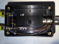
Here's mine, I used a 10K pot and 10K series resistors. It's made from plastic because I didn't want to connect the left and right shields. I had to make a metal fake unit to solder on because I didn't want to melt it, and then assemble it in the plastic one. It sounds great. ")
Attachments
Last edited:
You will come across people who claim that you need high quality fixed series resistors and a variable resistor to ground (shunt) for the best quality; they say this because they believe that the signal path is only through the series resistors. Completely untrue; you can ignore anything they say.
And we rehash this topic about once a month.
Is there an advantage to a properly designed stepped attenuator? You bet there is. Is there an advantage to "potentiometer not in the signal path" woo? No. In fact there are disadvantages, which were listed in the last thread about this topic.
There are a couple of things to look out for when using a passive preamp.
It is usually recommended to use a 10K pot. This is for good reason. It mitigates stray capacitive effects that can roll off high frequencies. You will be running a cable from the wiper lead of the pot. This creates a low pass filter.
It also minimizes pickup of stray magnetic fields from power supplies etc.
Understand that industry standard line level input impedance is 47 K. A lower input impedance will raise the low frequency input pole. Say your source (CD player etc ) has an output coupling capacitor of 10 uF. With 10K input impedance we get a -3dB frequency of 1.6 Hz. This is fine. But if it has say a 2.2 uF output capacitor, we get 7.2 Hz. 1 uF = 16 Hz. 16 Hz is pretty high for "hi-fi" applications. It will intrude on the audible band with phase shift and audible attenuation.
The irony is that a buffered volume control can offer higher input impedance, no affect on the frequency response, and drive a set of long cables without high frequency rolloff. In other words, lower distortion.
A lowish value pot does not prevent magnetic pickup, but electric field pickup.
OK.
Maybe there needs to be a sticky on this topic. People seem to think that a "passive preamp" is a free lunch.
The topic keeps coming up, in spite of the sticky. So apparently there is still some confusion.
I haven't posted in the thread because I don't want to rain on their parade. People are attached to their passive preamp so I leave it alone. People have put some real work into optimizing it and I do think that's important.
The aversion to op amps is understandable but what I've found out is that it's the circuit and layout that makes or breaks an op amp circuit. It's a learning process. Bypassing is critical and large onboard electrolytic caps are required to control the power supply spikes introduced by the class B output stage, if it's driving a heavy load. This is the same practice used in power amp design.
- Status
- This old topic is closed. If you want to reopen this topic, contact a moderator using the "Report Post" button.
- Home
- Source & Line
- Analog Line Level
- Passive Preamp/Volume Control